A servo is the only part in a beginner’s bin that argues back. Tell an LED to turn on and it turns on. Tell a bare DC motor to spin and it spins at whatever speed the voltage and the load negotiate between them. Tell a servo to go to 90 degrees and it goes to 90 degrees — and then it stays there while you push on the horn, shoving back against your thumb until you let go.
That stubbornness is not coming from your Arduino. Your sketch sends the same pulse whether the horn is where you asked or being twisted sideways by a servo arm under load. The correction happens entirely inside the servo, in a complete closed-loop control system packed into a case the size of a domino. It is probably the most sophisticated thing in a $5 starter kit, and almost nobody who uses one has any idea what the inside looks like.
What is actually in the case
Crack one open and you find four things: a small DC motor, a gear train, a potentiometer, and a little control circuit board. That is the whole inventory. No encoder, no microcontroller in the classic analog ones, no PID tuning you get to touch.
The motor is a plain brushed DC motor, the same kind of thing you would find in a cheap toy. On its own it spins fast and weak. The gear train fixes that, trading away most of that speed for torque at the output shaft — the same bargain covered in our guide to gear ratios and torque, just miniaturized and sealed in a box.
The potentiometer is the part that matters here, and it is the one nobody expects. It is mechanically coupled to the output shaft, so when the shaft rotates, the pot’s wiper rotates with it and the voltage on that wiper changes. That voltage is the servo’s entire sense of where it is. Not a position number, not degrees — a voltage. Every clever thing a servo does is built on top of that one analog value.
Your pulse is a request, not a command
The signal wire wants a repeating pulse at roughly 50 Hz — one pulse every 20 milliseconds, forever, for as long as you want the servo to hold position. What encodes the angle is the width of the high part of that pulse. About 1.5 milliseconds centers most servos. Roughly 1 ms and 2 ms hit the two extremes, though many servos will accept something closer to 0.5 ms to 2.5 ms and give you a wider sweep for it.
This trips people up because it looks like the PWM they already know. It is not the same thing. With ordinary PWM, the duty cycle is the message — 50% duty gets you half brightness. Here the duty cycle is almost irrelevant: a 1.5 ms pulse in a 20 ms frame is only 7.5% duty, and nudging the frame rate would not change the commanded angle at all. The servo is measuring one number, the length of the high pulse, and ignoring everything else.
The loop, in four steps
Here is what the control board does with that pulse, in a classic analog servo:
- A pulse-width-to-voltage converter turns the length of your incoming pulse into a voltage. Long pulse, higher voltage. That is the target.
- The potentiometer is already producing a voltage for where the shaft actually is. That is the measurement.
- A comparator looks at both. Its output is zero, positive, or negative — and it is only zero when the two input voltages are equal.
- That difference runs through an error amplifier and into an H-bridge motor driver, which spins the motor in whichever direction shrinks the error. The motor keeps turning until the error voltage is zero.
An H-bridge is just four switches arranged so current can be pushed through a motor in either direction — the same part we cover on its own in how motor drivers actually work. A servo has one built in, which is why you never wire a separate driver to a servo the way you would to a bare DC motor.
One detail in that chain explains a lot of real-world servo behavior: the drive going to the motor is proportional to the error. A big commanded move produces a big error, so the servo slams toward the target with everything it has. A two-degree nudge produces a tiny error, so the motor gets a tiny push — which is why small moves feel weak and sloppy on a cheap servo, and why a servo that happily lifts a load across a wide sweep can fail to make the last couple of degrees of it.
Deadband: why it does not chase every microsecond
If the loop corrected every difference no matter how small, the servo would never stop twitching. Electrical noise alone would keep the comparator flipping sign, and the motor would buzz and drain current all day holding still. So manufacturers build in a deadband: a window, expressed in microseconds, inside which the servo simply does not respond. If the error is smaller than the deadband, nothing moves.
Five microseconds is a commonly cited figure for analog servos. That number is more meaningful than it looks. If your usable range is about 1000 microseconds wide and the servo ignores anything under 5 of them, you get roughly 200 distinguishable steps across the full sweep — call it one degree of real resolution over 180 degrees. Commanding 90.3 degrees on a hobby servo is a fiction; the hardware cannot tell it from 90. If yours is buzzing anyway, that is usually power or mechanical, not the deadband, and we walk through it in why your servo is jittering.
This post contains affiliate links. If you buy through them, this site earns a commission at no extra cost to you.
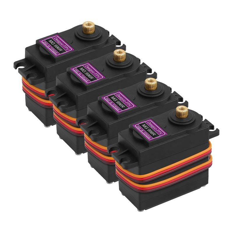
If you want to actually see any of this, you want a servo that is cheap enough to open. The MG996R is the standard mid-size hobby servo — metal gears, a case held together by four long screws, and a price low enough that sacrificing one to curiosity does not hurt. Pull the bottom cover and the control PCB is right there; pull the top and you can watch the gear train and find the potentiometer riding on the output shaft. Buying a multi-pack is the right call here precisely because one of them is going to become a teardown.
The workhorse mid-size servo. Metal gear train, standard three-wire hookup, and cheap enough per unit that you can dissect one and still have three to build with. Four screws in the bottom and the whole feedback loop is laid out in front of you.
Check Price on Amazon →Analog vs. digital: same loop, different referee
A digital servo is not a different machine. It has the same motor, the same gears, the same potentiometer. What changes is step three: instead of an analog comparator, there is a microcontroller reading the pot through an analog-to-digital converter and deciding what to do in software.
That one swap has consequences. An analog servo’s output to its motor is pulsed at the same 50 Hz as the signal coming in — it can only reconsider the situation fifty times a second. A digital servo is not bound by that, and can update the motor far faster, up to 500 Hz or more. Practically: more holding torque, better precision, a tighter deadband, noticeably higher current draw, and often an audible whine from the motor coils as the drive pulses at a frequency you can hear. A few digital servos drop the potentiometer entirely in favor of an optical or hall-effect encoder, which is a meaningfully different way to sense position — see how encoders work for why that matters.
If the phrase “decides what to do in software” sounds like it should involve proportional and derivative terms, it often does — a digital servo is running a control loop conceptually similar to the one in our PID explainer, just sealed in and not yours to tune.
Seeing the feedback signal for yourself
The frustrating thing about all of this is that the interesting signal is locked inside the case. You can solder onto the potentiometer wiper yourself and run a wire out to an analog pin — plenty of people do — but there is a part that ships that way on purpose. Parallax’s Feedback 360 servo brings the position signal out on a fourth wire, so your Arduino can read where the shaft actually is instead of assuming it got there. For anyone trying to understand closed-loop control rather than just use it, being able to log the commanded position and the real position side by side is the whole lesson in one graph.
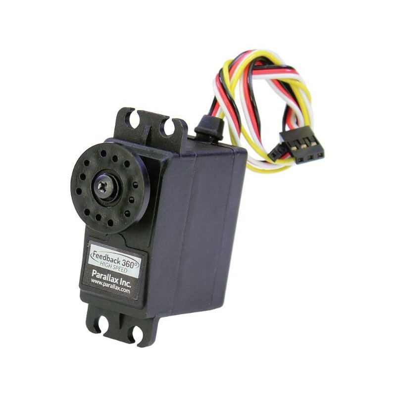
A continuous rotation servo with the internal position signal exposed on a fourth wire. You command it like any servo, but you can also read back where the shaft really is — which turns an invisible feedback loop into two numbers you can plot against each other.
Check Price on Amazon →Watching the loop respond without writing any code
There is a faster way to get a feel for deadband and response than iterating on a sketch. A servo tester is a knob that generates the pulse directly — no board, no upload cycle. Turn it slowly and you can feel exactly where the servo starts responding and where it ignores you, which is the deadband made physical. The three-channel kind also has a sweep mode and a center mode, and the center button is genuinely useful for setting up a servo horn at a known position before you bolt anything to it.
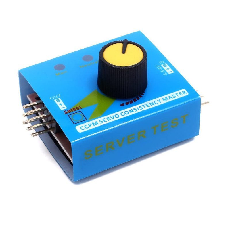
Manual, sweep, and center modes from a hardware knob. The fastest way to find a servo’s real travel limits and its deadband before you write a line of code — and a useful first check when a servo in a finished build stops behaving.
Check Price on Amazon →If you would rather do it in code, this sketch creeps through the microseconds around center one at a time. Watch the horn and the Serial Monitor together and you will see it sit perfectly still through several consecutive values, then jump — that jump is the edge of the deadband.
#include <Servo.h>

Servo s;

void setup() {
  s.attach(9);
  Serial.begin(9600);
}

void loop() {
  for (int us = 1450; us <= 1550; us++) {
    s.writeMicroseconds(us);   // commands pulse width directly
    Serial.println(us);
    delay(400);                // slow enough to watch
  }
}
Note the use of writeMicroseconds() rather than write(). The usual write(angle) call hides the pulse width behind a degrees abstraction, which is exactly the abstraction you are trying to see through here.
Where the loop runs out of road
Every bit of that correction is paid for in current, and the moment the servo most wants current is the moment it is furthest off target — exactly when the H-bridge is driving hardest. Standard hobby servos run on about 4.8 V to 6.0 V, and many modern ones will accept 7.4 V or more. What they will not tolerate is being fed from an Arduino’s 5 V pin. That regulator is not built to source a stalling servo’s inrush, and the resulting voltage sag will brown out the board that is supposed to be commanding it. Give servos their own supply with a shared ground — see fixing power issues when running multiple servos or motors for the wiring.
Once you know the loop is in there, a lot of servo weirdness stops being weird. The hum at rest is the loop hunting. The mushy last few degrees are the error amplifier running out of error to amplify. The one-degree granularity is the deadband. And the reason a servo holds position when a DC motor cannot is that somewhere inside that plastic case, a potentiometer is quietly telling a comparator it is not done yet.