PID control has a reputation problem. The name sounds like graduate-level control theory, the Wikipedia page opens with a Laplace transform, and half the forum threads about it are people arguing over tuning constants to three decimal places. So beginners assume it’s something to deal with “later.” Here’s the thing: PID is three lines of arithmetic, and whether you need it depends entirely on one question. Does your robot have to hold something at a target value while the world pushes back?
The problem PID solves
Say you want a wheel to spin at exactly 100 RPM. The obvious approach is to guess a motor power that produces 100 RPM on the bench and hardcode it. That works until the battery sags, the robot hits carpet, or the left motor turns out to be 8% weaker than the right one (they always are). Now your “straight line” curves.
The fix is closed-loop control: measure the actual speed, compare it to the target, and adjust motor power based on the difference. That difference is called the error, and it’s the only number PID cares about. Error = setpoint (what you want) minus measurement (what you’ve got). Everything else is about how to turn that error into a motor command without overshooting, oscillating, or settling a little short.
P, I, and D in plain terms
Proportional (P) is the part you’d invent yourself: push harder when the error is big, ease off as it shrinks. output = Kp * error. The constant Kp sets how aggressive that push is. P alone has a famous flaw. As error approaches zero, output approaches zero, so anything that needs sustained effort to hold position (a motor fighting friction, a heater fighting a cold room) settles just short of the target. That leftover gap is called steady-state error.
Integral (I) fixes that by adding up the error over time. If you’ve been 3 RPM slow for two seconds, that accumulated error keeps growing and the I term keeps nudging output upward until the gap actually closes. Ki sets how fast it accumulates. The classic failure here is integral windup: if the motor physically can’t reach the setpoint (say, the wheel is jammed), the integral keeps growing unbounded, and when the obstruction clears, the motor slams past the target. Good libraries clamp the integral to avoid this.
Derivative (D) looks at how fast the error is changing and pushes against rapid change. If you’re closing in on the setpoint quickly, D applies the brakes before you overshoot. Kd sets how much. It’s the term most beginners can leave at zero, because it amplifies sensor noise. A jittery ultrasonic reading turns into a jittery D term turns into a twitchy motor.
Add the three together and you have the whole algorithm: output = Kp*error + Ki*sum_of_error + Kd*change_in_error. That’s it. The math is trivial. The craft is in picking the three constants.
So, do you actually need it?
Probably not for your first robot, and I’d rather you build something that works than stall out tuning gains. A blunt rule:
- Skip it if the robot just reacts to discrete events. Obstacle avoidance (“see wall, turn left”) and a basic line follower that steers hard whenever a sensor leaves the line are bang-bang control, and bang-bang is fine at low speed. Our simple line-following robot build deliberately uses no PID at all.
- Use P only when you want smoother versions of those behaviors. A line follower that steers proportionally to how far off-center the line is will run visibly faster and smoother than one that jerks left and right. One constant to tune. Big payoff.
- Use full PID when the target is something that must be held against a disturbance: a self-balancing robot holding upright, two wheels holding matched speed so the robot drives straight, a heated bed holding 60°C, a drone holding level. These fail without it, not just “work worse.”
The one thing PID cannot do is invent a measurement. It needs a real sensor reading of the thing you’re controlling, at a decent rate. If you want matched wheel speeds, you need encoders on the motors. If you want balance, you need an angle sensor. Which brings us to the part you’d actually buy.
The sensor every PID beginner ends up with
This post contains affiliate links. If you buy through them, this site earns a commission at no extra cost to you.
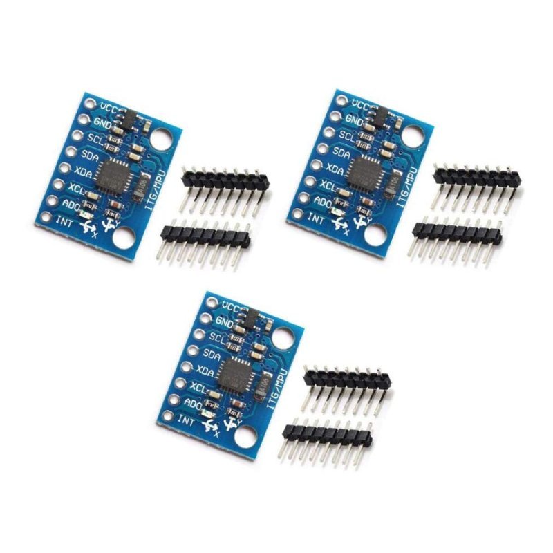
The canonical “I understand PID now” project is a self-balancing robot, and the sensor at the heart of nearly every one of them is the MPU-6050, sold on the GY-521 breakout board. It’s an IMU (inertial measurement unit) that packs a 3-axis gyroscope and a 3-axis accelerometer into one chip with 16-bit analog-to-digital converters, and it talks to your board over I2C, a two-wire bus where the Arduino asks the chip for data by address (0x68 by default, 0x69 if you tie the AD0 pin high). On an Uno, that’s SDA to A4 and SCL to A5. The GY-521 board has its own 3.3V regulator, so you feed VCC 5V straight from the Uno without a level shifter on the power side. If the 5V-vs-3.3V distinction is new to you, this explainer covers why it matters. The HiLetgo three-pack is the one I’d buy: the clones are all the same chip, and you will bend a header pin on your first one.
6-axis gyro + accelerometer on a breadboard-friendly breakout with onboard regulator. The default angle sensor for balancing robots, and cheap enough that three cost less than lunch.
Check Price on Amazon →Don’t write your own PID (yet)
Use Brett Beauregard’s PID library, installable from the Arduino IDE Library Manager (search “PID” and pick the one by Brett Beauregard, currently v1.2.1). It handles the boring failure modes for you: it clamps output to a range you set (default 0 to 255, which maps directly onto analogWrite()), it limits integral windup, and it computes on a fixed sample time (default 100 ms) so your Kd doesn’t change meaning every time you add a Serial.print to the loop. The whole API is three calls:
#include <PID_v1.h>

double Setpoint, Input, Output;
double Kp = 2, Ki = 5, Kd = 1;
PID myPID(&Input, &Output, &Setpoint, Kp, Ki, Kd, DIRECT);

void setup() {
  Setpoint = 100;              // the value you want
  myPID.SetMode(AUTOMATIC);    // turn the controller on
}

void loop() {
  Input = readYourSensor();    // the value you have
  myPID.Compute();             // fills in Output
  analogWrite(9, Output);      // do something with it
}
DIRECT means a bigger output pushes the input up (more motor power, more speed). If your system is backwards, like a cooling fan where more output means a lower temperature, use REVERSE. Those example gains are the library’s defaults, not magic numbers for your robot. You’ll change them.
Tuning without a textbook
Set Ki and Kd to zero. Raise Kp until the system oscillates steadily around the setpoint, then back it off to roughly half. Add Ki in small steps until the steady-state error disappears without a slow wobble creeping in. Only reach for Kd if you’re getting overshoot you can’t tame with Kp alone, and keep it small. That’s a hand-wavy version of the Ziegler–Nichols method, and for a hobby robot it gets you 90% of the way there in an afternoon. Plot the input against the setpoint the whole time, because tuning by eye from the wheel is guesswork and tuning from a graph is engineering.
One last caveat: a balancing robot also needs sensor fusion (combining the gyro and accelerometer into one stable angle with a complementary or Kalman filter) and fast, torquey motors. PID is the easy part of that build. But it’s the part that, once it clicks, changes how you think about every robot after it.