Here is the uncomfortable truth about every robot you have built so far: it has no idea where it is. You told a motor to spin for 800 milliseconds and you assumed that meant six inches of travel. On a smooth floor with a fresh battery, it might have. On carpet, with a battery at 60%, it was four inches. Your code never found out, because nothing was ever measuring.
An encoder is the part that closes that gap. It is a sensor bolted to a rotating shaft whose only job is to report how far that shaft has actually turned. Add one, and your robot stops guessing and starts knowing. That single change is the line between a robot that lurches roughly forward and one that drives straight, turns 90 degrees on command, and stops where you said to stop.
What an encoder actually does
Strip away the marketing and an incremental rotary encoder is a shaft with a patterned disc on it and a sensor watching that pattern go by. In an optical encoder the disc has slots cut in it and a beam of light gets chopped into pulses. In a magnetic encoder — which is what almost every hobby gearmotor uses — the disc is a ring of alternating magnetic poles and a Hall effect sensor reads them as they sweep past. Either way, the output is the same: a stream of square-wave pulses, one per feature on the disc.
Count pulses, and you know how far the shaft turned. Count pulses over time, and you know how fast. That is genuinely the whole idea. A single-channel encoder gets you exactly that much and no more, which is why you almost never see one on a robot — because it cannot tell you which direction the shaft went. The pulses look identical forwards and backwards.
Quadrature: two channels, 90 degrees apart
The fix is to use two sensors instead of one, offset so that their pulse trains are a quarter-cycle out of step. This is called quadrature, and the two outputs are conventionally labeled channel A and channel B. “Ninety degrees out of phase” means B’s rising edge lands squarely in the middle of A’s high period rather than at the same instant.
That offset is what encodes direction. When you catch a rising edge on A, you immediately read B’s current level. If A leads B, the shaft is turning one way; if B leads A, it is turning the other. Your code does not need to know anything about magnets or slots — it just needs four states and a rule for which transitions count as +1 and which count as −1. The result is a signed counter that goes up when the wheel rolls forward and back down when it rolls backward, including the case where your robot gets shoved and the wheel spins in reverse while the motor is still commanded forward. That is exactly the failure a timing-based robot never notices.
Quadrature also buys you resolution for free. Because there are four distinguishable edges per full A/B cycle, you can count all four instead of just one. This is where the spec-sheet acronyms come from: PPR (pulses per revolution) is how many cycles one channel produces per turn, and CPR (counts per revolution) is what actually lands in your counter. With full four-times decoding, CPR = 4 × PPR. A 100 PPR encoder read this way gives you 400 counts per revolution, which works out to 0.9° of resolution per count.
Why the gearbox is your secret weapon
Here is the part beginners consistently underestimate. On a typical hobby gearmotor, the encoder is mounted on the fast motor shaft, before the gear reduction — not on the slow output shaft your wheel bolts to. So the gear ratio multiplies your resolution. An encoder rated at 48 counts per revolution sounds pathetically coarse until you remember it is spinning a few hundred times for every single turn of the wheel. Effective resolution at the output shaft is 48 × the gear ratio, which on a heavily geared motor means several thousand counts per wheel revolution. That is more than enough to control position to a fraction of a millimeter of travel.
The tradeoff is pulse rate. A fast motor shaft with a decent CPR can generate several thousand interrupts per second, and an Arduino Uno running at 16 MHz has a finite budget for that. Two rules keep you out of trouble: put at least channel A on a real hardware interrupt pin (on the Uno that is pin 2 or pin 3), and keep the interrupt handler brutally short — increment a volatile long and get out. No Serial.print() inside an interrupt, ever. Do your math and your printing in the main loop. Paul Stoffregen’s widely used Encoder library handles the edge decoding for you and is worth reaching for before you hand-roll your own state machine.
One wiring note: most encoder gearmotors have six wires — two heavy ones for motor power, then encoder VCC, GND, A, and B. The encoder side runs on logic-level power, usually 5V, and is electrically separate from the motor supply. Do not feed 12V into the encoder’s VCC pin, and if you are driving one from an ESP32 rather than an Uno, check the encoder’s output voltage first — see 5V vs. 3.3V logic levels before you connect anything.
What encoders unlock
Three things, immediately. Drive straight: compare left and right counts and nudge the slower motor’s PWM up until they match — this fixes the classic “my robot veers left” problem that no amount of matched-motor shopping will solve. Turn a known amount: counts per wheel revolution and wheel circumference give you millimeters per count, so a 90° turn becomes arithmetic instead of a guessed delay. Actually use closed-loop control: an encoder is the measurement half of a feedback loop, which is the prerequisite for PID control. Without an encoder there is no error signal, and without an error signal PID has nothing to work with.
What to buy
This post contains affiliate links. If you buy through them, this site earns a commission at no extra cost to you.
There are two separate purchases here and people conflate them constantly. If your goal is to understand quadrature, you do not need a motor at all — you need a knob you can turn by hand while watching numbers change on your screen. A KY-040 module is a mechanical rotary encoder on a breakout board with a detented shaft, a knob cap, and a built-in push switch. At 20 pulses per revolution it is far too coarse for motion control, and it has the contact bounce every mechanical encoder has, but that is beside the point: it turns an abstract phase relationship into something you can feel clicking under your fingers. Buy the five-pack, because the first one will end up permanently wired into something.
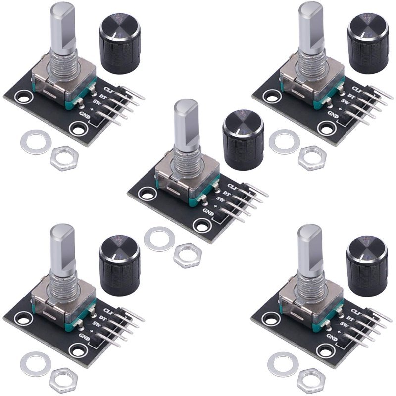
5V mechanical quadrature encoder on a breakout board, with knob caps and an integrated push button. 20 pulses per revolution — useless for a drivetrain, perfect for understanding one.
Check Price on Amazon →volatile long counter that increments or decrements on every CLK interrupt based on DT’s level at that instant, and print it in loop(). Turn the knob one detent clockwise: +1. One detent back: −1. Now the useful part — turn it fast and watch counts get skipped or double-fire. That is contact bounce, and watching it happen on a knob teaches you more about why real drivetrains use Hall sensors than any datasheet will.
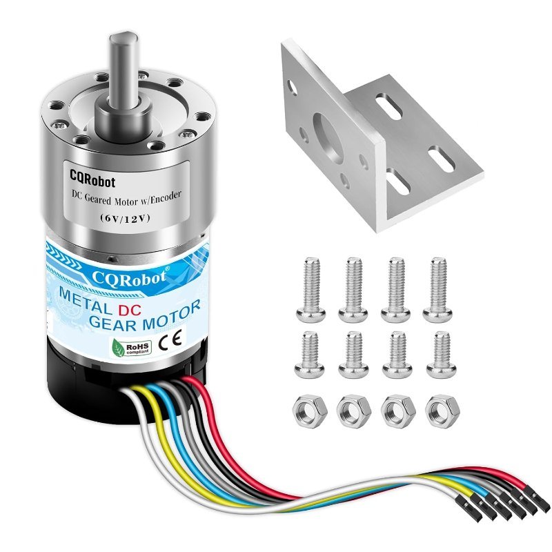
For an actual robot, you want the encoder and the motor sold as one unit, because retrofitting an encoder onto a bare gearmotor is a fussy mechanical job you do not want as your first encoder project. A 37mm metal gearmotor with a built-in two-channel Hall encoder is the standard answer: 64 counts per revolution at the motor shaft, multiplied by the gearbox, with the A and B outputs already broken out to wires. The 12V 40RPM version is slow and torquey, which is what you want for a chassis where you care about placement rather than speed. Note that it needs a 12V supply and a motor driver — the encoder gives you feedback, not power.
Metal 37mm gearmotor with an integrated quadrature Hall encoder, 64 CPR at the motor shaft — and because the gearbox is 270:1, that works out to 17,280 counts per turn of the output shaft. Six wires: red and black for motor power, plus encoder VCC, GND, A, and B. Slow and high-torque — built for precise positioning, not speed runs. Ships with the mounting bracket, which the cheap ones never do.
Check Price on Amazon →Do you need one?
Not for everything. A line follower reads the line, so it does not care how far it has traveled. An obstacle-avoiding rover that wanders until something is in front of it does not either. But the moment your project involves a specific distance, a specific angle, a specific speed held steady under changing load, or two motors that must agree with each other, timing-based control stops working and no amount of tuning delay values will save it. Encoders are how you stop writing code that hopes and start writing code that measures.