You are watching the Serial Monitor and your startup banner scrolls past a second time. Or the LED sequence you finally got working jumps back to step one for no reason. Or the robot drives forward, the servo turns, and the entire sketch starts over. Nothing in your code says reset, and yet the board plainly did.
Here is the part worth internalizing before you start rewriting loops: a randomly resetting Arduino is almost always a power problem, not a logic problem. The processor is not confused. It is being switched off and restarted, briefly, because its own supply voltage fell out from under it. Code bugs cause resets too, and I will get to those, but power is where you should look first because power is where the answer usually is.
First, make the board tell you why it reset
Stop guessing and ask the chip. The ATmega328P on an Uno keeps a one-byte register called MCUSR — the MCU Status Register — and after every reset it holds flags describing what caused it. Four bits matter:
- PORF (bit 0) — Power-on Reset Flag. The supply came up from nothing.
- EXTRF (bit 1) — External Reset Flag. Something pulled the RESET pin low: the button, or a wire.
- BORF (bit 2) — Brown-out Reset Flag. The supply dropped below the brown-out threshold while the chip was running. This is the one you are hunting.
- WDRF (bit 3) — Watchdog System Reset Flag. The watchdog timer expired and rebooted the board.
The datasheet’s own instruction is to read and then reset MCUSR as early as possible in the program. The flags are sticky — they persist until something clears them — so if you never clear the register you cannot tell this reset’s cause from last week’s.
byte resetCause;

void setup() {
  resetCause = MCUSR;   // read it first, before anything else
  MCUSR = 0;            // then clear it, so next time is readable

  Serial.begin(9600);
  Serial.print(F("Reset flags: 0b"));
  Serial.println(resetCause, BIN);

  if (resetCause & (1 << BORF))  Serial.println(F("-> BROWN-OUT (power dipped)"));
  if (resetCause & (1 << WDRF))  Serial.println(F("-> WATCHDOG timeout"));
  if (resetCause & (1 << EXTRF)) Serial.println(F("-> EXTERNAL (reset pin)"));
  if (resetCause & (1 << PORF))  Serial.println(F("-> POWER-ON"));
}
Two caveats, both real. More than one flag can be set at once — powering a board up can set PORF and BORF together, and holding the reset button down while applying power can set three — so read this as a ranked list of hints, checking the brown-out and watchdog bits before the power-on bit. And on a stock Uno the bootloader runs before your sketch does and can read or alter MCUSR on its way past, which makes the readout most trustworthy on a bare ATmega328P you wired up yourself. It is still worth printing on an Uno: a BORF that keeps reappearing is telling you something true.
Cause one: your 5 V rail is sagging
Brown-out means what it sounds like. The regulator cannot hold 5 V, the voltage dips below the level the chip is willing to run at, and the brown-out detector shuts the processor down and restarts it cleanly rather than letting it execute garbage. That is a feature. It is also the symptom you have been reading as a bug.
Arduino’s own published numbers for the Uno are worth having in front of you. The board will operate from an external supply of 6 to 20 volts, but the recommended range is 7 to 12. Below 7 V, Arduino’s documentation says flatly that the 5V pin may supply less than five volts and the board may become unstable. Above 12 V the regulator may overheat and damage the board. The 3.3V pin is capped at 50 mA. Each I/O pin is specified at 20 mA as a recommended operating condition, with 40 mA as the figure that must never be exceeded to avoid permanently damaging the microcontroller. If you want the longer version of that story, we covered battery vs. USB vs. wall adapter separately.
Notice what is not on that list: a maximum current for the 5V pin. Arduino does not publish one, because it depends on your input voltage and how hot you are willing to let the regulator get. What they do publish is the USB side — the board carries a resettable polyfuse, and if more than 500 mA is applied to the USB port the fuse breaks the connection until the overload is removed.
That 500 mA ceiling is what kills most beginner projects. A hobby micro servo draws very little sitting still, several hundred milliamps while it is actually moving a load, and more than that when it stalls against something. Two servos plus a laptop USB port is not a power supply, it is a reset generator. Same story for a DC motor through an L298N, a strip of addressable LEDs, or a relay board.
Add bulk capacitance where the current is actually drawn
A capacitor across the supply rails is a tiny local battery. When a servo snaps to a new position it wants a burst of current faster than the regulator and your wiring can deliver, and the rail dips for a few milliseconds — long enough to trip brown-out. A large electrolytic, 470 µF to 1000 µF, wired across the 5 V and ground rails physically close to the thing drawing the current, absorbs that burst. A small 0.1 µF ceramic in parallel handles the fast high-frequency noise the big slow electrolytic cannot. You want both, which is why every reference schematic has a fat can and a little disc sitting side by side.
Electrolytics are polarized: the striped side goes to ground, and installed backwards they fail loudly and permanently. Ceramics do not care which way round they go.
This post contains affiliate links. If you buy through them, this site earns a commission at no extra cost to you.
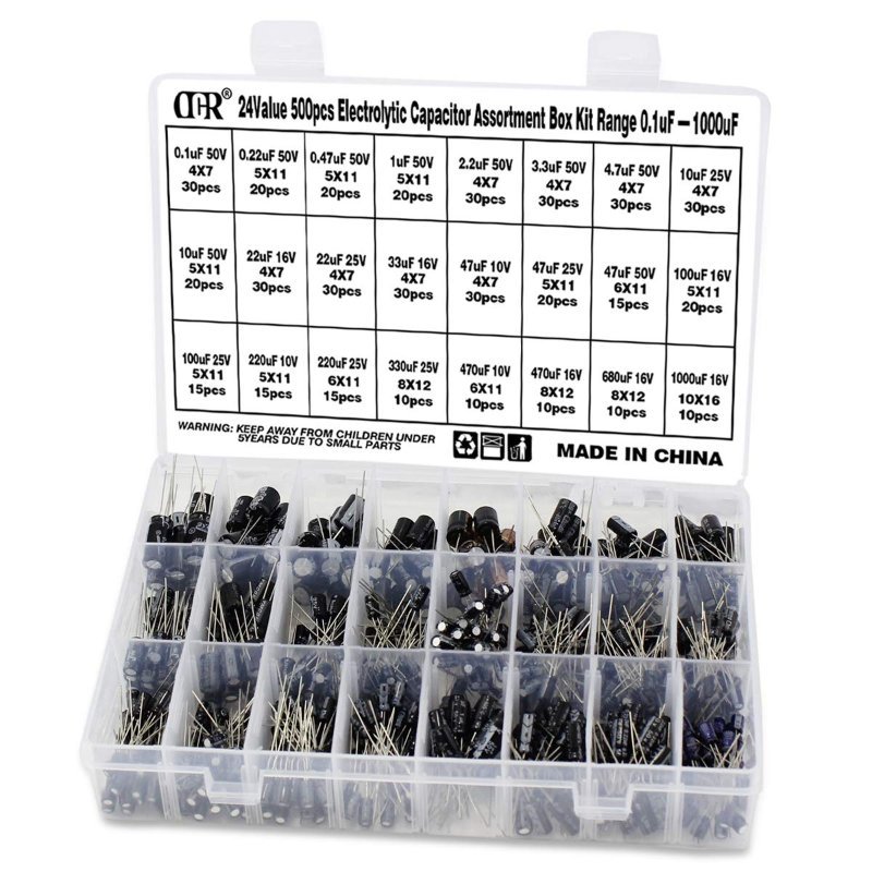
Twenty-four values from 0.1µF up to 1000µF in a sorted box, which covers both ends of the decoupling job without a parts order per project. Buying capacitors one value at a time is how you end up waiting two days to test a five-minute theory — get the box once and stop thinking about it.
Check Price on Amazon →Then give the motors their own supply
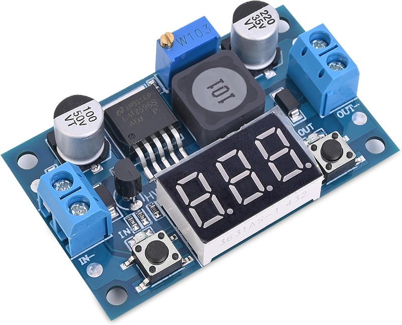
The actual fix is to stop asking the Uno’s little regulator to power things that are not the Uno. Run motors and servos from their own supply, tie the grounds together so both sides share a reference, and leave the board’s regulator doing nothing but running the board. An adjustable buck converter is the cheap way there: feed it 12 V from a wall adapter or 7.4 V from a 2S pack, turn the trimpot until the display reads 5.0 V, and wire that to the servo rail instead of to the board. Our longer walkthrough on fixing power issues with multiple servos or motors goes deeper on sizing the supply itself.
The common ground is not optional. Two supplies with no shared ground means your signal wires have no agreed-upon zero volts, and the servo will read your carefully timed pulses as noise. If pulse-width signalling is still new to you, start with how Arduino fakes an analog output with PWM.
One warning that comes straight from Arduino: do not backfeed the 5V or 3.3V pins. Supplying voltage through those pins bypasses the regulator and can damage your board, and Arduino explicitly advises against it. Power the board through USB or the barrel jack, and power the motors separately.
An LM2596 module that takes 4–40 V in and puts out an adjustable 1.25–37 V, with an onboard voltmeter so you can dial in exactly 5.0 V without clipping a meter on. The built-in display is the part that earns the small premium over a bare module — setting a buck converter blind, then wiring it to something you care about, is a bad habit.
Check Price on Amazon →Cause two: the watchdog, and code that quietly runs out of room
If MCUSR comes back with WDRF set, the watchdog timer rebooted you. The watchdog is a hardware countdown: if your code does not reset it before it expires, it assumes the sketch has hung and restarts the board. If you enabled it on purpose, that is it doing its job and you have a loop that occasionally takes too long. If you never touched it, a persistent WDRF is unusual and points at a library doing it on your behalf — but it is worth printing the flag so you can rule the watchdog out in a single reading instead of wondering.
The more common software cause sets no flag at all, which is exactly why it is so maddening. The ATmega328P has 2 KB of SRAM. Two kilobytes, total, for your variables, your buffers, and the call stack, with the heap and the stack growing toward each other from opposite ends of that space. Heavy use of the String class allocates and frees chunks over and over, fragmenting what is left; eventually an allocation collides with the stack and the behavior is formally undefined. In practice, undefined very often looks like a random reset.
Two habits fix most of it. Wrap every string literal you print in the F() macro — Serial.println(F("Ready")) keeps those characters in flash instead of copying them into SRAM at startup, and a chatty sketch can easily waste a quarter of its RAM on banner text. And prefer fixed char arrays over String concatenation in anything that runs inside loop(). If variables and memory are still fuzzy, our Arduino programming basics post is the place to start.
Cause three: the boring physical stuff
Before you redesign your power system, rule out the dumb things, because the dumb things are extremely common:
- A charge-only or thin-conductor USB cable. Enough voltage drop in the cable alone can push a marginal setup under the line. Swap in a known-good data cable before you theorize about anything else.
- A jumper that is almost out of the breadboard. Breadboard contacts loosen with reuse. The row that worked yesterday now connects only when the wire sits just so, and every bump is a power cycle.
- Signal and reset wiring running alongside motor leads. A spinning brushed motor is a small radio transmitter. Keep those runs short and route them away from motor wiring.
- A stray wire strand or a screwdriver briefly bridging 5 V and ground. Instant reset, no evidence left behind, and you will blame your code for an hour.
- A USB hub shared with other hungry devices. You are splitting a budget that was already tight.
Measure it instead of guessing
Everything above goes much faster when you can see the voltage rather than infer it. An inline USB meter sits between the port and your board and shows volts and amps live, with nothing to set up. Run the sketch that misbehaves, watch the display as the servo moves, and if the voltage dips while the current spikes, you are finished guessing: it is brown-out, and the two fixes above apply.
Its one real limitation is that it measures what the USB port is delivering, not what the 5 V rail inside your circuit is doing six inches later. For that you want probes on the rail itself, which means a meter — we put a batch of those through their paces in the digital multimeter guide.
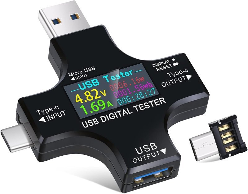
A color-screen inline meter reading 3.6–30 V and 0–5.1 A, with both USB-A and Type-C so it works with whatever cable your board actually uses. It turns "I think my power is sagging" into a number you can watch move, which is the single fastest way to end a reset hunt.
Check Price on Amazon →The short version
- Read
MCUSRat the top ofsetup()and print it. BORF means power, full stop on the code theories. - Unplug every motor, servo, and LED strip. If the resets stop, it was never your code.
- Add 470–1000 µF plus a 0.1 µF ceramic across the rail, at the load.
- Move the load onto its own supply, with the grounds tied together.
- Only then go audit your sketch for SRAM use and the watchdog.
A resetting board feels like betrayal. It is usually the opposite — the chip protecting you from a supply that cannot keep up. And a supply that cannot keep up is a far easier problem than a bug you cannot find.