A WiFi-capable dual-core microcontroller with a 2-megapixel camera and a microSD slot, for about the price of two coffees. The AI-Thinker ESP32-CAM is one of the most genuinely remarkable price-to-capability ratios in hobby electronics, and it is also one of the most frustrating boards a beginner can buy. Both of those things are true at once, and which one you experience depends almost entirely on whether you understand what the board leaves out before you order it.
I want to be clear about what this review is: not a teardown of one vendor’s clone, because the ESP32-CAM is a reference module that a dozen sellers reproduce to the same AI-Thinker spec. It is a review of the design, the tradeoffs baked into the board itself, and what you actually need to buy alongside it to have a working camera instead of a $10 paperweight.
What You Get for Ten Dollars
The module is built around an ESP-32S, carrying an ESP32-D0WD — a dual-core Xtensa LX6 running at 160 or 240 MHz, with WiFi and Bluetooth on board. Alongside the 520 KB of internal SRAM, AI-Thinker’s own spec sheet lists 4 MB of external PSRAM and 32 Mbit of flash. That PSRAM matters more than it sounds like it should: the standard camera example checks for it at boot and only enables the OV2640’s full UXGA frame size if it finds it, dropping back to SVGA if it does not. Some Amazon listings advertise 8 MB PSRAM variants; the AI-Thinker reference figure is 4 MB, so treat the larger number as a claim to verify rather than a guarantee.
The camera is an OV2640, 2 MP, which will output JPEG directly — and that is the quiet reason this board works at all. A microcontroller with 520 KB of RAM cannot hold a raw UXGA frame, let alone compress one. The sensor does the JPEG encoding itself and hands the ESP32 a finished, already-small file. Strip that away and the whole project would be impossible at this price.
There is also an onboard microSD slot (the spec sheet claims support up to 4 GB), a white flash LED, and an etched 2 dBi PCB antenna with an IPEX connector next to it for an external one. Power draw is modest: AI-Thinker publishes 180 mA at 5 V with the flash off, 310 mA with the flash at maximum brightness, and as low as 6 mA in deep sleep.
The Camera Eats Most of the Board
Here is the first tradeoff nobody mentions in the listings. Driving an 8-bit parallel camera sensor takes a lot of pins, and on this module the camera consumes fifteen of them: PWDN on GPIO 32, XCLK on GPIO 0, the I2C-style control lines SIOD and SIOC on GPIO 26 and 27, eight data lines on GPIOs 5, 18, 19, 21, 36, 39, 34 and 35, plus VSYNC on 25, HREF on 23, and PCLK on 22.
(SIOD and SIOC are the sensor’s configuration bus — a two-wire data-and-clock pair, the same arrangement as any I2C sensor. The ESP32 writes register values over it to tell the OV2640 what resolution and format to produce. It is not the path the image data takes; that is the eight parallel data lines.)
What is left on the headers is nine usable IO pins: IO1, IO2, IO3, IO4, IO12, IO13, IO14, IO15 and IO16 — and most of those are already spoken for. IO1 and IO3 are the serial TX and RX you need for uploading and for the Serial Monitor. IO2, IO4, IO12, IO13, IO14 and IO15 are the microSD card’s data, clock and command lines. Run the camera and the SD card together and you are down to roughly two free pins. That is the real constraint on ESP32-CAM projects, and it is why so many builds that look like they should fit on one board end up needing a second microcontroller.
There Is No USB Port. That Is the Whole Catch.
The bare ESP32-CAM has no USB connector and no onboard USB-to-serial chip. To get a sketch onto it you wire an external serial adapter to the header: the board’s U0T (transmit) to the adapter’s RXD, U0R (receive) to the adapter’s TXD — a crossover, since one side’s output is the other side’s input — grounds tied together, and power on either the 5V or 3V3 pin. Then, critically, you jumper GPIO 0 to ground before powering up, because GPIO 0 held low at boot is what tells the ESP32 to enter its bootloader instead of running your sketch. Upload, remove the jumper, reset. Leave it grounded and your code never runs.
The default upload baud rate is 115200. If the IDE hangs on Connecting.... and then reports a timeout waiting for the packet header, that almost always means GPIO 0 is not actually grounded or the adapter is miswired — pressing the module’s reset button the moment “Connecting” appears is the standard trick for catching the window.
This post contains affiliate links. If you buy through them, this site earns a commission at no extra cost to you.
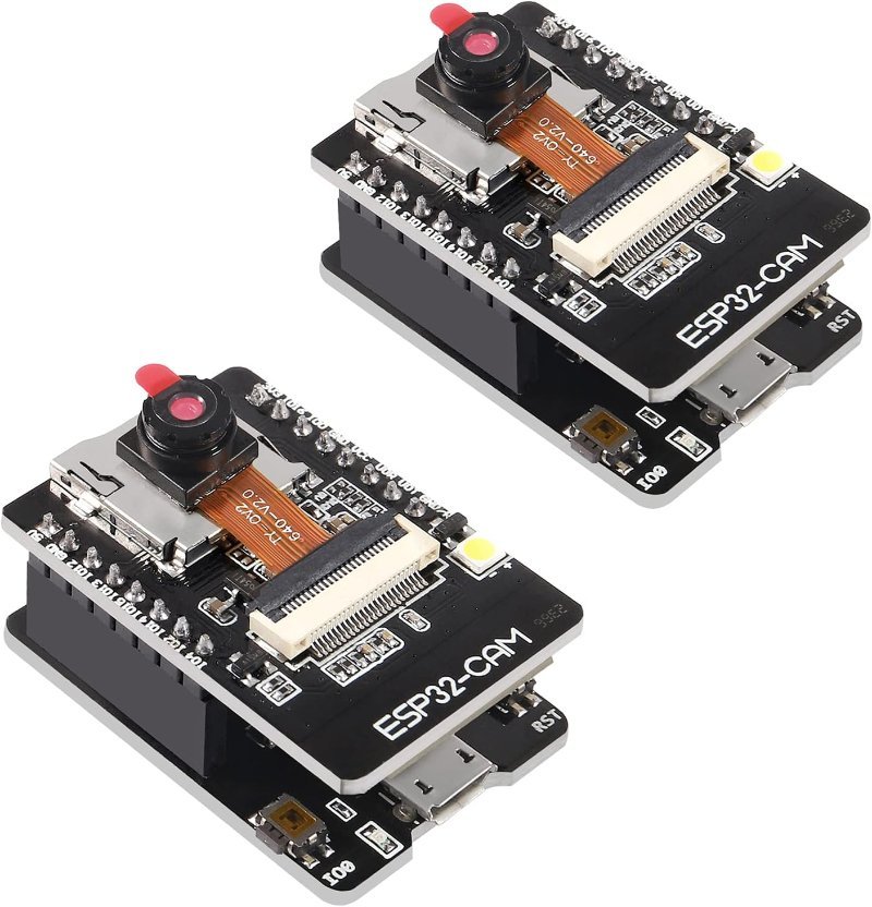
All of that is survivable, but you should not have to survive it on your first evening. Buy the version that ships with an ESP32-CAM-MB base board instead. The MB is a carrier the module drops onto: it has a micro USB port, a CH340G USB-to-serial chip, and the GPIO 0 boot logic handled in hardware, so uploading becomes plug in, hit Upload, done. It costs a few dollars more than a bare board and removes the single biggest reason people give up on this module.
Two modules and two MB programmer bases. The MB turns a fiddly five-wire adapter dance into a micro USB cable, and having a spare module is more useful than it sounds — these boards run hot and get bricked by bad uploads.
Check Price on Amazon →If you already own a USB-to-serial adapter, or you want the cheapest possible entry to find out whether you like this board, a single bare module is about as low as the barrier to entry goes in this hobby.
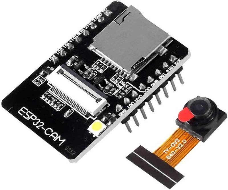
The reference module on its own: ESP32-S, OV2640, 4 MB PSRAM, microSD slot, IPEX antenna connector. Right call only if you already have a serial adapter on the bench.
Check Price on Amazon →And if you don’t have an adapter, get one with a selectable output voltage. There is an unresolved argument in the community about whether to program this board at 3.3 V or 5 V — some guides swear uploads are more reliable at 3.3 V, others insist 5 V is the only way the board behaves — and an adapter with a jumper lets you simply try both instead of picking a side. (If the 3.3 V versus 5 V distinction isn’t familiar yet, our guide to 5V vs. 3.3V logic levels covers why it matters.) Avoid CH340-based adapters for this particular job; multiple ESP32-CAM guides report them failing where CP2102 and FTDI adapters work.
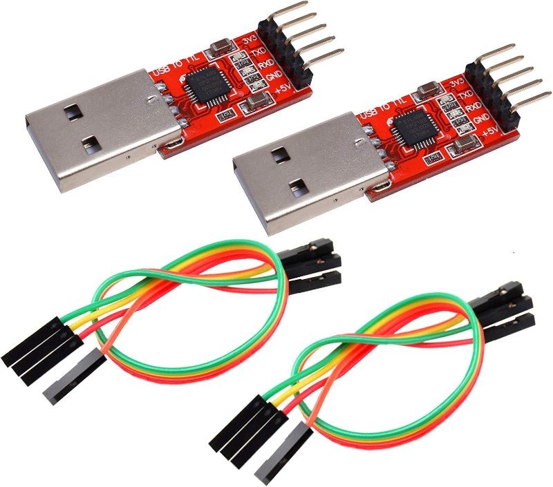
Five-pin CP2102 adapter with a 3.3V/5V jumper and jumper wires included. The jumper is the feature — it lets you test both power options without rewiring anything.
Check Price on Amazon →Brownout: The Error Everyone Hits First
Search any ESP32-CAM forum and the same message dominates: Brownout detector was triggered. The ESP32 has an internal supervisor that resets the chip when the supply voltage sags below a threshold, and this board trips it constantly — because WiFi transmit bursts and camera initialization both pull current spikes well above that placid 180 mA average, and a laptop USB port routed through a long, thin cable cannot deliver them.
The fixes, in the order worth trying: a shorter and better-quality USB cable; a different port, or a powered USB hub (a passive one accomplishes nothing); and powering the board from its 5V pin rather than 3V3. Published guidance on how much current to provide ranges from “at least 500 mA” to a flat recommendation of 5 V at 2 A — I would budget at least 1 A and not think about it again. Our rundown of battery vs. USB vs. wall adapter power applies directly here.
You will also find advice to simply disable the brownout detector in code:
#include "soc/soc.h"
#include "soc/rtc_cntl_reg.h"

void setup() {
  WRITE_PERI_REG(RTC_CNTL_BROWN_OUT_REG, 0);  // disable brownout detector
  // ...rest of setup
}
This works, in the sense that the error message stops. It does not fix the power problem — it silences the alarm that was telling you about it, and you trade a clear reset message for mysterious crashes and corrupted frames later. Treat it as a diagnostic step, not a solution.
The microSD Slot and the Flash LED Share a Pin
A small design wart worth knowing before it confuses you: GPIO 4 drives the onboard white flash LED and serves as the microSD card’s DATA1 line. Initialize the SD card in its default 4-bit mode and the flash LED will flicker or glow during card access, and the LED’s load can make SD writes unreliable. The usual workaround is to mount the card in 1-bit mode, which leaves GPIO 4 free for the LED. If you are planning to log images or data to that card, our SD card data logger guide covers the file-handling side.
The Antenna Choice Is a Soldering Job
The module has both an etched PCB antenna (2 dBi) and an IPEX/U.FL connector for an external one, and you can only use one at a time. Which one is active is set by a 0-ohm resistor bridging one of two pad positions on the underside of the board. Moving it means desoldering a component roughly the size of a grain of sand and reflowing it one position over. If your project needs the range of an external antenna, buy a module where the vendor has already done it, or accept that you are doing fine-pitch SMD rework. Range problems on this board are frequently just the PCB antenna being asked to do too much through a wall.
So Should You Buy One?
Yes — with the right expectations. The ESP32-CAM is not a beginner’s first board; it is an excellent second board. If you have already blinked an LED, read a sensor, and understand what a boot pin does, this module is an extraordinary amount of capability for the money, and the projects it unlocks (motion-triggered cameras, WiFi doorbells, timelapse rigs, plant monitors that actually show you the plant) are a real step up from blinking lights.
If it is your first microcontroller, start somewhere with a USB port and twenty free pins, and come back to this one. The board is cheap because the design spends every available resource on the camera. That is a smart tradeoff, not a flaw — but you have to know it was made. For a sense of what a more conventional ESP32 board looks like, our ESP32 dev board review covers the ones with a USB port and pins to spare.