Blinking an LED proves your board works. Reading a sensor proves your board can notice something. That’s a much bigger jump than it looks, and it’s where a lot of people stall out — the blink sketch works, the sensor sketch compiles, and the Serial Monitor spits out a wall of numbers that mean nothing.
The fix isn’t a better sensor. It’s understanding what your board is actually measuring, which is almost never the thing you think it is.
Your board can’t read light, heat, or distance. It reads voltage.
An Arduino Uno has exactly one trick for the analog world: a 10-bit analog-to-digital converter, or ADC. Point it at one of the A0–A5 pins, call analogRead(), and it compares the voltage on that pin against a 5V reference and hands you back a whole number from 0 to 1023. Nothing else. Not lux, not degrees, not centimeters — a count.
Ten bits gives you 1024 possible steps across 5 volts, which works out to about 4.9 millivolts per step. That’s your entire resolution. A change smaller than ~5mV on the pin is invisible to the Uno; it’ll return the same number. Knowing that figure tells you immediately whether a sensor is even worth wiring up: if the thing you want to detect only moves the voltage by 2mV, no amount of clever code will recover it.
This is also why board choice changes your numbers. An ESP32 runs a 12-bit ADC against a 3.3V rail, so the same physical voltage produces a completely different count — and feeding it 5V will damage it. If you’re mixing boards, read 5V vs. 3.3V Logic Levels, Explained before you wire anything. Worth noting: analogRead() defaults to 10-bit output on every Arduino board for backward compatibility, even on newer hardware that can do better, unless you explicitly call analogReadResolution().
Start with a photoresistor, because it fails in instructive ways
A photoresistor — also called an LDR, or light-dependent resistor — is a two-legged disc of cadmium sulfide whose resistance drops when light hits it. The workhorse part is the GL5528: roughly 10–20 kΩ in ordinary room light, climbing toward 1 MΩ in the dark. No polarity, no library, no datasheet archaeology. It costs pennies and it responds to you waving your hand over it, which makes debugging obvious in a way a temperature sensor never is.
This post contains affiliate links. If you buy through them, this site earns a commission at no extra cost to you.
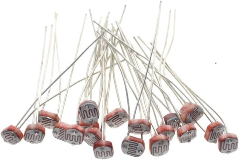
A hundred of the standard 5mm LDR for the price of a coffee. Buy the bulk pack deliberately — you will lose some in the carpet, snap a leg off at least one, and eventually want three of them in the same circuit comparing readings from different directions.
Check Price on Amazon →The part nobody tells you: a photoresistor alone does nothing
Here’s the step that breaks most first attempts. Your Arduino measures voltage, and a photoresistor changes resistance. Those aren’t the same thing. Wire an LDR straight from 5V to A0 and the pin just sits at 5V regardless of light, because there’s nothing for the resistance to divide against.
You need a voltage divider: LDR from 5V down to the junction, a fixed resistor from that junction down to ground, and A0 tapped off the junction in the middle. Now the two resistances split the 5V between them in proportion, and the voltage at the middle moves as the LDR changes. A 10 kΩ fixed resistor is the conventional partner for a GL5528 because it sits near the middle of the LDR’s working range, which puts your readings in the fat part of the 0–1023 scale instead of pinned at one end.
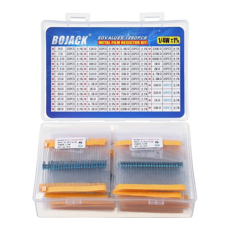
Buy resistors by the assortment, not the value. You will need a 10k today, a 220Ω for the next LED, and a 4.7k further down this page — and a labeled book of fifty values costs less than three separate trips to order single parts.
Getting the numbers out: Serial Monitor, carefully
The whole sketch is four lines of real work: Serial.begin(9600) in setup(), then Serial.println(analogRead(A0)) and a short delay() in loop(). Open Tools → Serial Monitor and you should see a column of numbers.
Two things bite people here. First, the baud rate in the Serial Monitor’s dropdown has to match the number you passed to Serial.begin() exactly — mismatch it and you get garbage characters, not silence, which is a confusing failure because it looks like a broken sensor rather than a broken setting. Second, put a delay(200) or similar in the loop. analogRead() takes roughly 100 microseconds, so without a delay you’re printing something like ten thousand readings a second and the Monitor becomes unreadable noise.
512 does not mean “half”
Once numbers are scrolling, the temptation is to convert them into units. Resist it for a minute. Cover the sensor completely, write down the number. Shine a phone flashlight on it, write down that number. Leave it in normal room light, write that down too. On a typical GL5528 with a 10k divider you’ll find the usable range is nothing like 0–1023 — it might be 60 in the dark and 900 under a flashlight, with everyday indoor light landing somewhere around 300.
Those three measured endpoints are your real scale, and map() exists to stretch them into whatever range you want. This is the single most useful habit to build early: calibrate against the room the project actually lives in, don’t trust the theoretical span. Photoresistors also vary noticeably part-to-part, so two LDRs from the same bag will not agree with each other — another reason the bulk pack is handy.
When you want a number you can actually trust
Analog sensors teach you the pipeline. Digital sensors let you skip it. A DS18B20 has the ADC and the conversion math built into the chip, so instead of a raw count you get degrees Celsius over a one-wire digital protocol, accurate to ±0.5°C across the −10°C to +85°C range where most projects live. It needs one 4.7 kΩ resistor pulled up between the data line and VCC, the OneWire and DallasTemperature libraries, and that’s the whole setup.
The genuinely clever part: every DS18B20 ships with a unique 64-bit address burned in at the factory, so you can hang a dozen of them off a single Arduino pin and address each one individually. Try that with analog sensors and you run out of A-pins at six. The trade-off is speed — a full 12-bit conversion takes up to 750 milliseconds, so this is not the part for anything that changes fast.
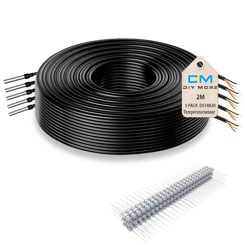
Sealed stainless probes on 2-meter leads, and the pack includes the 4.7k pull-ups you need — which is the one part people forget and then spend an evening debugging. Waterproof matters more than it sounds: soil, aquariums, and brew kettles are where beginner temperature projects actually end up.
Check Price on Amazon →Serial.println() the DS18B20’s degrees and the thermistor’s raw analogRead() count together and cup your hand around both. You’ll watch one report a real temperature while the other reports a number that only becomes a temperature after you do the math yourself. That gap is exactly what you’re paying for in a digital sensor.
The four things that go wrong first
- A floating pin. An analog input with nothing connected doesn’t read 0 — it picks up ambient electrical noise and returns numbers that drift and wander convincingly. If your “sensor” gives plausible-looking random values, check that it’s actually connected before you debug the code.
- No common ground. If the sensor is powered from anywhere other than the Arduino, its ground and the Arduino’s ground must be tied together. Without a shared reference, “voltage” is meaningless and the readings are garbage.
- Missing the divider resistor entirely. The reading sits pinned at 1023 and never moves. This is the single most common first-sensor failure.
- Reading an analog value off a digital pin.
analogRead(2)doesn’t do what you want. Only A0–A5 are wired to the ADC on an Uno.
Get a photoresistor, a 10k resistor, and three honest calibration readings written on a scrap of paper, and you’ve learned the thing that transfers: every analog sensor you ever wire up is the same pattern with a different physical quantity on the front end. The sensor changes. The pipeline doesn’t.