Most beginner robots don’t fail because the code is wrong. They fail because the power is wrong. The classic symptom looks like a software bug — the robot boots, runs fine for two seconds, then the serial monitor spews garbage and the whole thing restarts the instant the motors spin up. That’s not your loop. That’s your battery sagging below what the board needs to stay alive.
Power is the least glamorous part of robotics and the part that quietly decides whether anything else you built works. Here’s what actually matters.
Voltage, current, capacity: three numbers that do three different jobs
Voltage (V) is what your parts demand. An Arduino Uno wants 7–12V on VIN, a TT gear motor is happy at 6V, a servo wants 5–6V. Voltage is a matching problem: too little and things brown out, too much and you cook something. It’s the one number you can’t fudge.
Current (A or mA) is what your parts draw, and it’s not a number you choose — the load decides it. Your job is to supply a source that can deliver it without collapsing. An SG90 micro servo pulls maybe 10mA sitting still and around 650mA when you stall it against a wall. A small DC gear motor idles near 150mA and can spike past an amp the moment it starts or hits a curb. Two motors plus two servos plus a board is a peak budget of roughly 2–3A, even though the average is far lower.
Capacity (mAh) is how long it lasts. A 3000mAh pack can theoretically deliver 3000mA for one hour, or 600mA for five. In practice you get maybe 80% of the label before the voltage sags too far to be useful, so budget four hours, not five.
There’s a fourth number on lithium packs worth knowing: the C rating. Multiply it by the capacity in amp-hours to get the maximum continuous current the pack can deliver. A 3Ah pack rated 10C can push 30A. For a desktop robot that’s wildly more headroom than you need — which is exactly why lithium packs don’t sag the way a handful of AAs does.
Why your board resets when the motors start
Every battery has internal resistance. When current spikes, the voltage at the terminals drops — that’s the sag. Alkaline AAs have relatively high internal resistance, so a motor startup surge can yank a 9V pack down to 6V for a few milliseconds. The Arduino’s regulator, which needs headroom above 5V to do its job, can’t hold the 5V rail. The ATmega328P’s brownout detector sees the rail fall below its threshold (typically 2.7V) and does exactly what it’s designed to do: it resets the chip rather than letting it execute garbage.
The fix is almost never in software. It’s giving the motors their own supply path, keeping the logic rail stable, and tying the grounds together. If your motor is misbehaving in a way that smells electrical, our motor troubleshooting checklist walks the same territory from the symptom end.
One battery, two rails, one ground
The standard robot power architecture is simpler than it sounds. One pack feeds two branches: a motor rail that goes straight to your motor driver’s power input, and a logic rail that gets regulated down to a clean 5V for the microcontroller and sensors. The two branches must share a common ground, or your driver won’t see your control signals as valid at all — the signal pin and the driver have to agree on what “zero volts” means.
This is also where a lot of 3.3V boards get hurt: an ESP32 fed from a rail meant for a 5V part is a bad afternoon. If you’re mixing board families, read our explainer on 5V vs. 3.3V logic levels before you wire anything together.
What to actually buy
This post contains affiliate links. If you buy through them, this site earns a commission at no extra cost to you.
Start here if you’re on a breadboard-and-chassis budget. Six AA cells in series gives you 9V alkaline (or 7.2V with NiMH rechargeables, which is arguably better — lower internal resistance, less sag). A holder with a switch and a 2.1×5.5mm barrel plug drops straight into an Uno’s jack with zero soldering, which makes it the fastest way to cut the USB cord on a first robot. It is not a great long-term answer — AAs sag under motor loads and you’ll go through them — but for a line-follower that runs for twenty minutes at a demo, it’s fine and it’s cheap.

Six AA cells, an on/off switch, and a barrel plug that fits the Uno’s jack directly. Five of them costs less than one decent lithium pack, so you can leave one wired into every chassis on the shelf.
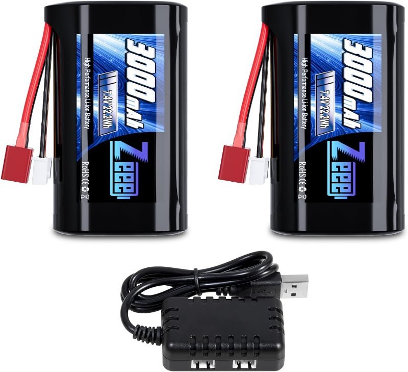
Check Price on Amazon →The upgrade that fixes the reset problem. A 2S lithium pack is 7.4V nominal — 8.4V fully charged, around 6V when it’s done — which sits comfortably in the Uno’s VIN window for most of its discharge curve, and has the low internal resistance to swallow motor surges without dragging the rail down. I’d point beginners at Li-ion rather than LiPo specifically: slightly lower discharge ceiling, considerably more forgiving about being left on a shelf at half charge. 3000mAh is a genuinely long afternoon for a small rover. Buy one that ships with its own balance charger — charging lithium cells off anything other than a proper balance charger is how people end up with a puffy pack.
7.4V nominal, 3000mAh, and a charger in the box. The right default for any robot with motors on it — enough headroom for the Uno’s regulator and enough current to keep the logic rail steady when the wheels bite.
Check Price on Amazon →Stop running everything through the Arduino’s regulator
This is the single most common power mistake, and it’s worth understanding rather than just avoiding. The Uno R3’s onboard regulator is a linear regulator — an NCP1117 — and a linear regulator makes 5V by burning off everything above 5V as heat. Feed it 12V and draw 500mA, and the chip is dissipating (12 − 5) × 0.5 = 3.5 watts in a package the size of a grain of rice. It will hit thermal shutdown, and your robot will die mid-run for no reason your code can explain.
A switching buck converter solves this properly. Instead of burning the difference, it chops the input on and off at high frequency and filters the result, hitting 85–90% efficiency and staying cool while doing it. Wire your pack to a buck module, set the output to 5V, feed that into the Arduino’s 5V pin (bypassing the onboard regulator entirely) and into your servo rail. Get the version with the voltmeter display — you set the output with a trimpot, and being able to read the actual number while you turn it beats guessing with a multimeter in your third hand.
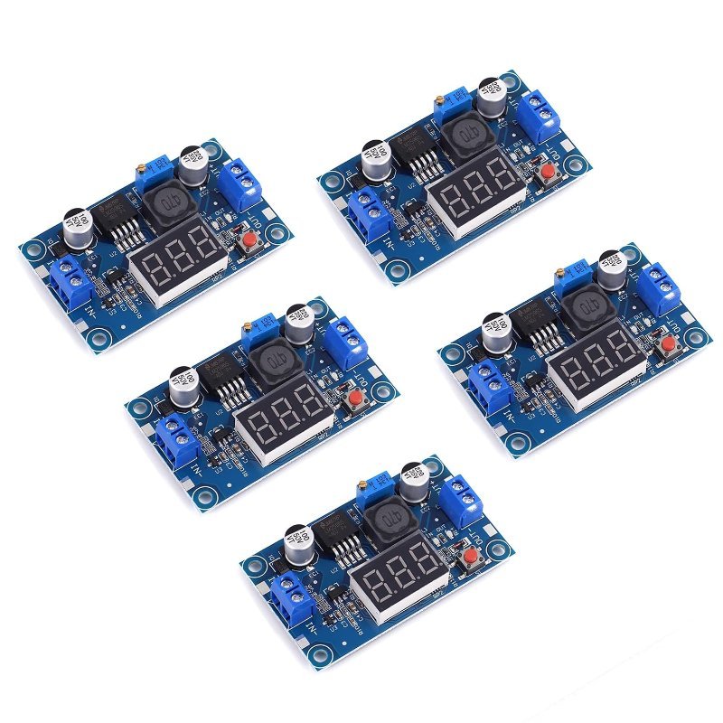
4–40V in, 1.25–37V out, 2A, with a display so you can dial the output in by eye. The part that turns a raw battery into a usable 5V rail without cooking your board’s regulator.
Check Price on Amazon →getCurrent_mA() to the Serial Monitor — you’ll find out your robot’s real peak draw in about thirty seconds, and it’s almost always higher than you guessed.
Sizing the pack without overthinking it
Add up what each part draws in normal operation — not stall, normal. Board and sensors, call it 100mA. Two small gear motors cruising, maybe 400mA together. A servo panning a sensor, another 100mA average. That’s 600mA. Divide your pack capacity by that and take 80%: a 3000mAh pack gives you around four hours of runtime.
Then size for peak separately, because that’s a different failure. Peak is what determines whether the robot resets, and it’s roughly your stall current: two motors at 1A each plus a servo at 650mA is around 2.7A for a few milliseconds. Your pack’s C rating and your buck converter’s current limit both need to clear that number, or you’re back to mysterious reboots.
Get those two numbers right and an enormous category of “my robot is haunted” problems simply stops happening. Power first, then code.