A Bluetooth robot car is the first project where a beginner build stops feeling like a beginner build. You stop watching a breadboard and start driving something across the floor from your phone. It is also, mechanically, one of the simplest things on this site — there is no computer vision, no PID loop, no sensor fusion. Four wires carry motor commands, two wires carry radio data, and that is the entire architecture.
The reason people get stuck is almost never the concept. It is one of three specific things: they wire the Bluetooth module to the wrong pins and can never upload code again, they feed 5V into a pin that wants 3.3V, or they power the motors off the Arduino and wonder why the board keeps rebooting. All three are avoidable if you know about them going in.
What "Bluetooth-controlled" actually means here
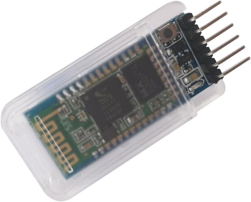
The HC-05 module this build is centered on is not doing anything clever. It runs Bluetooth 2.0+EDR using the Serial Port Profile — SPP — which is a standard that makes a radio link behave exactly like a serial cable. Whatever your phone sends over the connection comes out of the module’s TX pin as plain serial data. Whatever the Arduino writes to the module’s RX pin shows up on your phone. That is the whole abstraction.
Practically, this means you are not learning a new API. If you have ever used Serial.println() to print sensor readings to the Serial Monitor, you already know how to talk to an HC-05. You send a single character — F for forward, L for left, S for stop — and your sketch runs a switch statement on it. Single characters instead of words, because parsing strings on an Uno is a waste of a build this simple.
One thing to settle before you buy anything: SPP does not work with an iPhone. Apple restricts classic Bluetooth serial to MFi-certified hardware, so an HC-05 or HC-06 will not pair with iOS at all. Android, Windows, and macOS are fine. If you own an iPhone, skip ahead — there is a fix, and it is a different module, not a different app.
The chassis: buy the cheap one on purpose
This is the part people overspend on. A 2WD acrylic chassis with two yellow TT gearmotors, two wheels, a caster, and a battery box is the correct starting platform, and it costs about as much as lunch. The motors are unremarkable — roughly 1:48 gear ratio, no position feedback, mild speed mismatch between the left and right units — and that is fine, because the mismatch is a useful problem. Your car will drift slightly to one side, you will compensate in software by trimming one motor’s PWM value down, and you will have learned more than a perfectly matched kit would have taught you.
This post contains affiliate links. If you buy through them, this site earns a commission at no extra cost to you.
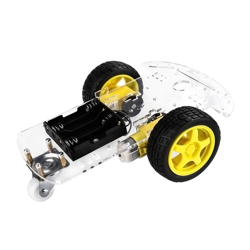
Two TT gearmotors, wheels, caster, battery box, and an acrylic deck with enough mounting holes to bolt an Uno and a driver board straight on. The included speed encoder discs are a bonus you can ignore on day one and come back to later.
Check Price on Amazon →If you want to compare platforms more carefully before committing — 2WD versus 4WD, acrylic versus metal — we went through that in detail in the robot chassis kit comparison. For a Bluetooth car specifically, 2WD is the right answer. Differential steering with two wheels and a caster turns in place, which is exactly what you want when you are driving by thumb.
The motor driver: the Arduino cannot do this itself
An Arduino output pin can source about 20mA safely. A TT gearmotor pulls somewhere between 150mA unloaded and well over an amp when stalled against a table leg. Wiring a motor directly to a pin destroys the pin, and possibly the microcontroller behind it. You need an H-bridge — a switching arrangement of four transistors that can connect a motor to the supply in either polarity, which is how you get forward and reverse from a single motor without rewiring anything.
The L298N board is the default for this build, and it deserves the position. Dual H-bridge, so it drives both motors from one board, 5V to 46V supply range, and up to 2A per channel. Two caveats worth knowing before you wire it: without a heatsink, plan on about 1A continuous per channel before thermal shutdown becomes a real risk, and the L298N’s bipolar output stage eats voltage. The datasheet’s worst case is roughly 3.2V of drop at 1A and nearly 4.9V at 2A. Budget for it.
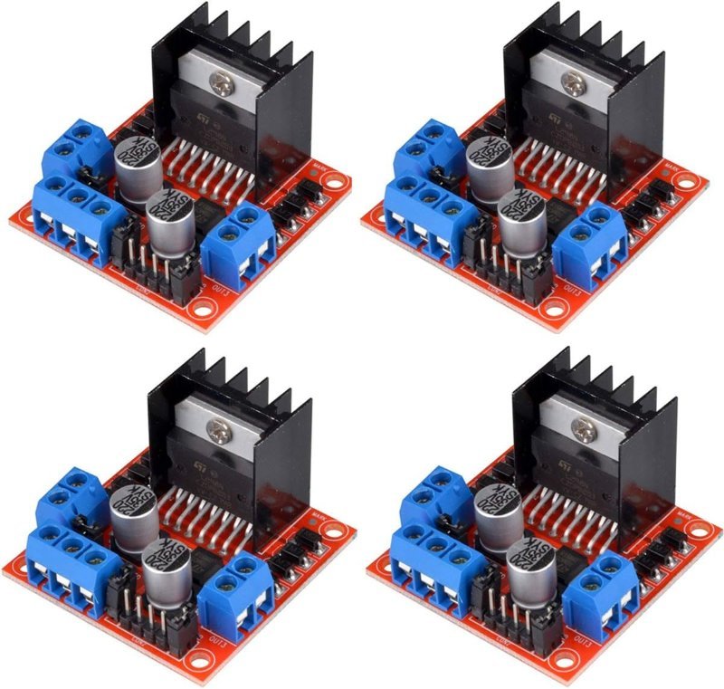
The standard beginner H-bridge, with screw terminals, an onboard 5V regulator, and ENA/ENB jumpers you pull off when you want PWM speed control. Buying four is not overkill — this is the board most likely to get cooked by a wiring mistake.
Check Price on Amazon →analogWrite(9, 160) instead of a plain digitalWrite. That is pulse-width modulation — the pin switches on and off thousands of times a second, and the fraction of time it spends on sets the effective motor speed. Try 80, 160, and 255 and find the lowest value that still gets your car moving from a standstill; that number is your real minimum throttle, and hardcoding anything below it is why "forward" sometimes does nothing. If the transistor side of this is still fuzzy, how motor drivers actually work covers what is happening inside the chip.
The Bluetooth module: one resistor divider, two pins to avoid
Here is where builds die. The HC-05’s VCC pin is forgiving — there is an AMS1117 regulator onboard, so anything from about 3.6V to 6V is fine and the Arduino’s 5V rail works directly. The RX pin is not forgiving. It is a 3.3V logic input with no protection in front of it, and feeding it the Arduino’s 5V TX signal degrades the CSR chip over time: dropped characters first, then a dead module.
The fix is two resistors. A 1kΩ in series and a 2kΩ to ground forms a divider that turns 5V into 3.33V, which the module reads as a clean HIGH. The other direction needs nothing — the HC-05 outputs 3.3V on TX, and a 5V Arduino already registers that as HIGH. If the asymmetry there seems arbitrary, our explainer on 5V vs. 3.3V logic levels lays out where the thresholds actually sit.
The second trap: do not wire the HC-05 to pins 0 and 1. Those are the Uno’s hardware serial pins, shared with the USB-to-serial chip, and a module sitting on them will fight the bootloader every time you try to upload. Use SoftwareSerial on pins 2 and 3 instead, at 9600 baud — the HC-05’s default in data mode. The module on this board has a small button that holds the KEY pin high on power-up, which drops it into AT command mode at 38400 baud if you ever want to rename it or change the pairing PIN.
Master/slave capable, unlike the slave-only HC-06, and the onboard button makes entering AT mode a non-event instead of a soldering exercise. Pairs with any Android phone and a free serial terminal app — no custom app required to get moving.
Check Price on Amazon →SoftwareSerial at 9600 baud reading single characters. Only the app on the phone side differs, and a generic BLE terminal app will drive it on day one.
Power: the failure that looks like a code bug
The single most common symptom in this build is a car that lurches forward and then resets, or one that responds to Bluetooth commands until the motors start and then goes silent. Both are power problems wearing a costume.
Motors draw current in spikes, especially on startup and stall. If the motors and the Arduino share one supply, those spikes drag the rail below the point where the microcontroller stays alive, and the board browns out and reboots — which drops the Bluetooth connection, which looks like a radio problem. Give the L298N its own battery pack on the 12V screw terminal and let it feed logic power back to the Arduino through its onboard regulator, or run two packs entirely.
Size the pack with the voltage drop in mind. A 4×AA pack puts out about 6V; subtract the L298N’s roughly 2V and your 6V motors see 4V, which is why so many first builds feel underpowered. Six AAs (9V) or a 2S lithium pack (7.4V) lands the motors much closer to their rated voltage. Alkalines will also sag hard under motor load — rechargeable NiMH or lithium cells hold voltage far better here.
What the first drive is actually like
Underwhelming, and then not. The first successful test is usually a car that only goes forward, because you wired one motor’s terminals backward and reverse cancels out. Swap the two wires on that motor at the screw terminal, or flip the two digitalWrite states for that channel in software — either fixes it, and doing it in software is faster.
Then it drifts. Both motors get the same PWM value and the car still curves, because no two TT motors are identical. Drop one side to 220 while the other stays at 255 and drive it again. Somewhere around the third adjustment you will realize you are hand-tuning an open-loop controller, which is the exact problem PID control exists to solve — and the encoder discs that came in the chassis kit suddenly stop looking like packing material.
That is the real value of this project. It is not the remote-control car. It is that a Bluetooth car is the shortest path to running into four or five genuinely foundational problems — logic levels, H-bridges, PWM, power budgeting, open-loop error — while something is physically moving across your floor, which makes every one of them stick.