An empty I2C scanner output is one of the more demoralizing results in hobby electronics, because it tells you almost nothing. The sketch compiles. The Serial Monitor opens. And then: Done. Nothing found. No error, no hint, no partial credit.
The good news is that scanning is a genuinely binary test, and the list of things that can make it come up empty is short — nine items, and I have personally been burned by every one of them. Here is the order I check them in now, starting with the checks that cost nothing.
First, understand what the scanner is actually doing
A scanner sketch is not magic and it is not doing anything clever. It walks every valid address on the bus, starts a write to each one, and immediately ends it without sending any data. Wire.endTransmission() then reports whether anything out there pulled the data line low to acknowledge that address.
Per the Arduino reference, that function returns 0 for success, 1 for “data too long to fit in transmit buffer,” 2 for “received NACK on transmit of address,” 3 for “received NACK on transmit of data,” 4 for “other error,” and 5 for timeout. For scanning you care about exactly two of those. 0 means something answered. 2 means nothing did — which is the correct, expected result for the ~110 addresses that have nothing attached to them.
#include <Wire.h>

void setup() {
  Wire.begin();
  Serial.begin(9600);
  while (!Serial);

  Serial.println("Scanning...");
  for (uint8_t addr = 0x08; addr <= 0x77; addr++) {
    Wire.beginTransmission(addr);
    if (Wire.endTransmission() == 0) {
      Serial.print("Found device at 0x");
      Serial.println(addr, HEX);
    }
  }
  Serial.println("Done.");
}

void loop() {}
Note the loop bounds, because they matter. The usable 7-bit device range is 0x08 through 0x77; addresses 0x00–0x07 and 0x78–0x7F are reserved by the I2C specification and are deliberately skipped. If you wrote your own scanner and started at zero, you are not finding extra devices, you are just poking at addresses no device is allowed to use.
1. Prove the bus works with a device you trust
Before you spend an hour debugging the sensor you actually care about, find out whether the problem is the sensor or the bus. Unplug everything, wire up one device you are confident works, and scan again. If it shows up, your wiring and your board are fine and the fault is in the other module. If it does not show up, stop looking at the sensor entirely — you have a bus problem, and nothing you do to the sensor will fix it.
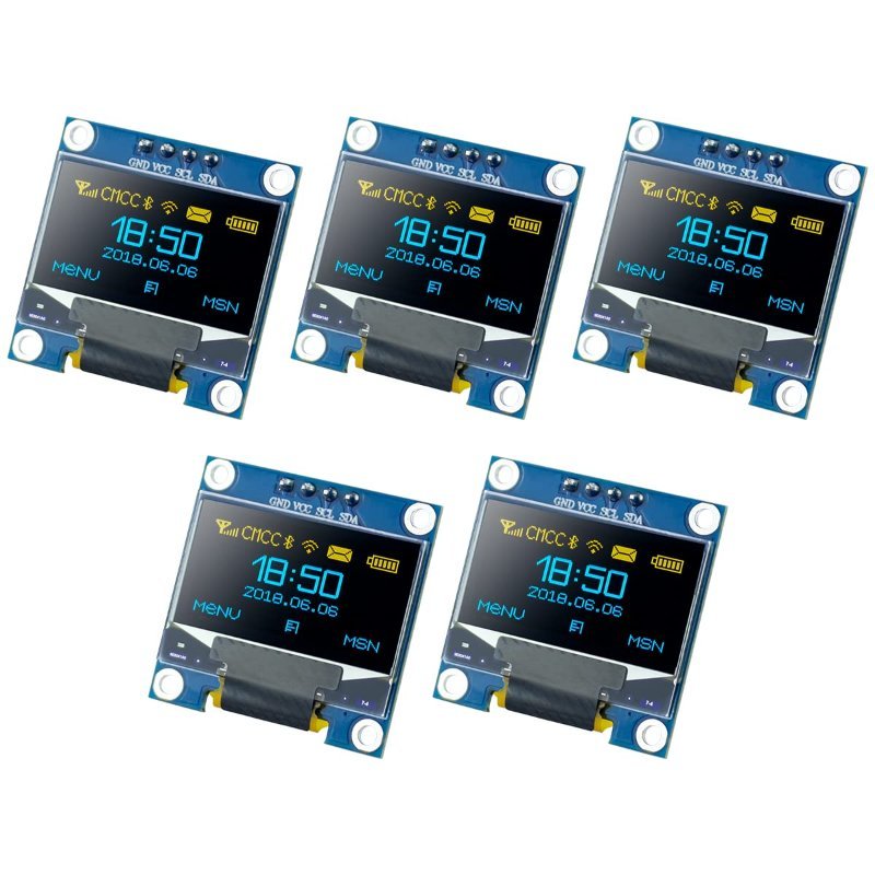
This is the single best argument for keeping a cheap SSD1306 OLED module in the parts drawer. It is a known quantity, it answers at a documented address, and it has one enormous diagnostic advantage over a sensor: it lights up. That gives you a second, independent signal about whether the thing is powered and talking, instead of relying on the scanner alone.
This post contains affiliate links. If you buy through them, this site earns a commission at no extra cost to you.
Five 128×64 I2C OLED modules for the price of a sandwich. Keep one permanently on the breadboard as your known-good bus test — if it answers, the bus is alive; if it does not, you have found your real problem. The spares are genuinely useful, since these are the displays half of beginner projects end up using anyway.
Check Price on Amazon →0x3C (some modules ship strapped to 0x3D instead — the SSD1306’s SA0 pin selects between the two, and both are normal). Now the instructive part: add a second identical OLED to the same two wires and scan again. You will still see exactly one address, because two devices acknowledging the same address is electrically indistinguishable from one device. That is precisely the problem a TCA9548A I2C multiplexer exists to solve — it puts each identical device on its own switched branch of the bus so you can talk to them one at a time.
2. You are wired to the wrong pins
I2C lives on fixed pins on most boards, and those pins are not labeled SDA and SCL on every one of them. On an Uno they are hiding in the analog header, which catches people constantly.
Board                SDA        SCL
-------------------  ---------  ---------
Arduino Uno / Nano   A4         A5
Arduino Mega 2560    20         21
ESP32 (generic)      GPIO21     GPIO22   <- varies by board!
On the ESP32 the defaults are GPIO21 and GPIO22, but Espressif’s own documentation is explicit that “the default pins may vary from board to board” — and plenty of ESP32 dev boards, especially the ones with a display or battery circuitry on them, route I2C somewhere else entirely. You do not have to guess. The ESP32 Arduino core lets you pass the pins directly with Wire.begin(sdaPin, sclPin, frequency), or call Wire.setPins(sdaPin, sclPin) before Wire.begin().
And check the dumb one, because it is the most common: SDA and SCL swapped. It is a two-wire bus, the pins are adjacent on both ends, and reversing them produces exactly the symptom you are looking at — nothing found, no error, no clue.
3. Missing pull-up resistors
Here is the thing about I2C that explains most of its failure modes: nothing on the bus ever drives a line high. Devices can only pull the lines low. Resistors pull them back up to the supply voltage, and that is what defines the idle state. Strip the pull-ups out and the bus has no high level at all, so nothing can signal anything. The scanner finds nothing because there is nothing to find.
Most breakout boards you buy already have pull-ups soldered on, which is why this normally works without you ever thinking about it. Two situations break that comfortable arrangement. The first is a bare chip, or a stripped-down board that omits them — you need to add your own, one resistor from SDA to the bus voltage and one from SCL. 4.7kΩ is the standard starting point for a 5V bus at 100 kHz, and anything in the 1k–4.7k range covers most hobby situations.
The second is sneakier and shows up once a project grows: every module you add brings its own pull-ups, and they sit in parallel. Five boards carrying 10k pull-ups each give you an effective 2k, which can load the bus hard enough to round off the signal edges and cause intermittent dropouts that look like flaky wiring. If you are running a long chain of modules, the fix is to desolder the pull-ups on all but one.
Do not count on your microcontroller’s internal pull-ups to rescue you either. They are weak by design; PJRC’s Wire library notes that where on-chip pull-ups are used at all, they “may be sufficient for short wires to a single device,” which is a long way from an endorsement.
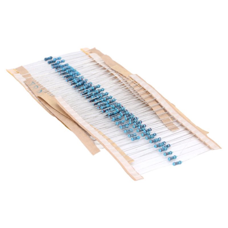
Thirty values from 10Ω to 1MΩ, which means the 4.7k you need for pull-ups is in the box along with every other value you will reach for. Buying resistors one value at a time is a false economy — you spend more on shipping than on parts, and you always need the one you did not order.
Check Price on Amazon →4. A 3.3V device on a 5V bus
Plenty of I2C sensors are 3.3V-only parts. Plenty of beginner boards are 5V. Because I2C is open-drain — the pull-ups set the high level, not the chip — you can sometimes mix the two and apparently get away with it, which is exactly what makes this bug so maddening. It half-works. The device acknowledges once and then stops, or returns garbage, or runs for a week and then quietly dies.
Two rules keep it clean. If the device is 3.3V-only, power its pull-ups from 3.3V rather than 5V, so the bus never swings above what the part can tolerate. And if you genuinely need a 5V controller and 3.3V devices on the same bus, use a bidirectional level shifter built for I2C. The common four-channel BSS138 board is the right tool here specifically because it works in both directions on an open-drain line, which a simple resistor divider does not. If the whole 5V-versus-3.3V question is new to you, we took it apart in detail in 5V vs. 3.3V logic levels, explained.
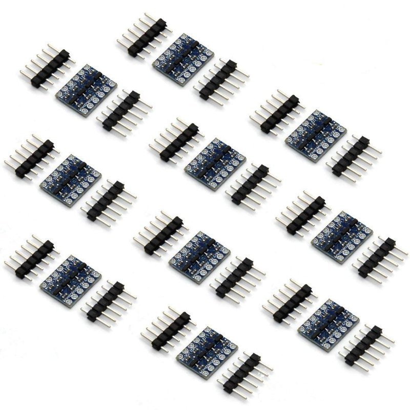
The standard BSS138-based shifter, ten to a bag, which is the right quantity because you will want one on every mixed-voltage project you build. Two channels handle SDA and SCL with two left over for whatever else needs translating. Note that these ship unsoldered, so budget a few minutes with an iron.
Check Price on Amazon →5. No common ground
Trivially easy to miss and trivially easy to fix: if your sensor is powered from a separate supply or a different board, SDA and SCL are meaningless without a shared ground reference. Two wires is not enough. You need three. This is the one that ambushes people the moment they move a working breadboard circuit onto a robot with its own battery pack — the logic was fine, the grounds just stopped being the same ground.
6. The address in the datasheet is not the address Wire wants
The Arduino Wire library uses 7-bit addresses. A great many datasheets print the 8-bit form instead, which is the 7-bit address shifted left one position with the read/write bit stuck on the end. So the same chip shows up in the wild as both 0x68 and 0xD0, depending on who wrote the document you are reading.
If your sketch targets the 8-bit value, it will never match anything, and you get the specially confusing version of this bug where the scanner cheerfully reports a device while your own code insists nothing is there. The fix is arithmetic: shift the 8-bit write address right one bit, or just divide by two. 0xD0 >> 1 is 0x68. When the scanner finds something at an address you do not recognize, work the shift in both directions before you conclude you have the wrong part.
7. Two devices claiming the same address
Scanning is how you find this one, and code cannot fix it. If two modules are hardwired to the same address, the bus has no way to distinguish them — they both acknowledge, and you see one device where you expected two.
Most sensors anticipate this. Many modules carry an address-select pad or jumper on the back, with the silkscreen showing which pad to bridge: BME280 and BMP280 boards live at 0x76 or 0x77, and the SSD1306 picks between 0x3C and 0x3D based on its SA0 pin. Check your module’s own datasheet for which two addresses it can take rather than assuming — the jumper may also have been bridged at the factory in a way you did not expect. When a part offers no alternate address at all, a multiplexer is the only way out.
8. The device is not actually powered
An unpowered device cannot acknowledge, and a scanner reports that identically to a device that is not there. Measure VCC at the module itself, not at the board pin — a loose breadboard connection or a jumper pushed into the wrong row produces the exact same empty scan, and a breadboard circuit that looks right but is not is its own whole category of problem. While you are at it, confirm the module wants the voltage you are feeding it; a 3.3V part on 5V may have already stopped answering permanently.
9. Bad joints and over-long wires
I2C was designed for short runs between chips on a board, not for the half-meter of loose jumper wire we all end up using. Every centimeter adds capacitance, which slows the rise time the pull-ups have to fight against, and at some point the bus simply stops working. Shorten the wires, or lower the clock speed. And if the module came as a bare board with a separate header strip, inspect your solder joints under good light — a cold joint on SDA is indistinguishable from no device at all.
The 60-second checklist
- Scan with a single known-good device attached. Does anything show up?
- Confirm you are on the right pins for your specific board, and that SDA and SCL are not swapped.
- Confirm pull-ups exist on the bus — one module with them is enough, zero is fatal.
- Confirm the device and the pull-ups are running at a voltage the device tolerates.
- Confirm a shared ground between every board involved.
- Confirm you are using the 7-bit address, not the 8-bit one.
- Confirm no two devices share an address.
- Measure VCC at the module itself.
- Shorten the wires and reflow any joint you are not sure about.
If you have been through all nine and still have an empty scan, the next step is to stop guessing and look at the actual signal — whether SCL is clocking at all, and whether anything is pulling SDA low. A cheap logic analyzer turns that from speculation into a picture, and we rounded up the ones worth owning in the best USB logic analyzers under $50. But be honest with yourself about the odds first. In my experience it is the pins, the pull-ups, or the ground, roughly in that order, and it is almost never anything exotic.