A breadboard circuit that doesn’t work looks exactly like a breadboard circuit that does. That’s the whole problem. There’s no error message, no smoke, no blinking anything to tell you which one of your forty connections is lying to you — just an LED sitting there dark while you re-read a sketch that was fine the entire time.
Before you rewrite a single line of that code, start with the board. Not because breadboards are bad, but because they hide every connection under a plastic lid and happily let you believe things about them that aren’t true. Here are the assumptions that turn out to be wrong most often, roughly in the order I’d check them.
1. Your power rails are split down the middle
This is the single most common one, and it’s the most maddening because the board looks continuous. On most full-size 830-point breadboards, each long power rail is physically broken in half near the center. Manufacturers do it on purpose so you can run 5V on the top half of a rail and 3.3V on the bottom half without them fighting each other — useful once you know about it, invisible until you do.
The tell is printed right on the board: look at the red and blue stripes running along the edge. If there’s a gap in the colored line about halfway down, often with a slightly wider space between holes there, that rail is split. So if you plugged your Arduino’s 5V pin into the top-left of the red rail and your sensor into the bottom-right of the same rail, those two holes may never have been connected to each other at all. Your sensor has simply never had power.
The fix takes two jumper wires: one bridging the break in the + rail, one bridging the break in the − rail. Do it the day you unbox a board and you’ll never chase this bug again. Not every board is split — some run continuous end to end — which is exactly why you want to check rather than assume.
2. The center channel is a wall, not a decoration
That trench down the middle of the board is 0.3 inches wide because that’s the standard body width of a DIP chip — the rectangular black integrated circuits with legs down both sides. The channel lets you straddle one so each side’s pins land in different rows instead of shorting together.
For debugging, what matters is that the channel electrically separates the top half of every column from the bottom half. Each column gives you five connected holes above the trench and five connected holes below it: ten holes in a straight line, two completely separate nets. Plug one leg of a resistor into row 12 above the channel and run the wire that’s supposed to meet it into row 12 below, and you have built a circuit that goes nowhere. It looks perfect. It’s two islands.
For reference, the main grid on an 830-point board is 630 tie points in a 30 × 10 matrix on a 0.1-inch (2.54 mm) pitch. The two distribution strips along the edges add the other 200 points, which is where the “four power rails” on the spec sheet comes from — two rails per strip, one strip per side.
3. Both legs of a component landed in the same group
A group of five holes is one electrical node. Everything plugged into those five holes is the same point in the circuit. So if both legs of your resistor went into the same group, that resistor isn’t in your circuit — you’ve replaced it with a plain piece of wire. Same for an LED: both legs in one group is a dead short across it, and it will never light no matter what your code does.
Components need to span rows, always. One leg in one group, the other leg in a different group. This one catches people constantly with small parts whose legs are close together, because the natural thing to do with a component that doesn’t want to spread is to let it sit neatly in two adjacent holes — which are in the same group.
4. You’re using stranded wire, or the wrong gauge
Breadboard clips are built for a specific conductor diameter. ELEGOO rates these boards for 21–26 AWG, which is roughly 0.4–0.7 mm. 22 AWG solid core sits right in the middle of that window, which is why practically every jumper kit sold for breadboarding uses it.
Stranded wire is the one to avoid. When you push it into a hole, the individual strands splay out — one or two catch the clip while the rest fold over outside the hole. Sometimes it works. Sometimes it works until you nudge the board, which is worse, because now you have an intermittent fault instead of an obvious one. If stranded is all you’ve got, tin the ends with solder so the tip behaves like a solid pin.
Going too thick is more damaging than going too thin. Forcing an oversized power lead or a fat component leg into a clip spreads it permanently, and every 22 AWG wire that goes into that hole afterward will sit loose. You’ve quietly created a bad hole that will haunt three future projects.
5. The clips are simply worn out
Breadboard contacts are small spring-metal clips, and springs have a finite number of good insertions in them. On a cheap clone board, “finite” can mean “not very many.” The signature symptom is a circuit that works when you press down on a wire and stops when you let go, or one that behaves differently after you move the board. That’s mechanical, not electrical, and no amount of rewriting your sketch will touch it.
You can occasionally rescue a specific hole by gently squeezing that row with needle-nose pliers to close the clip back up. Gently — over-compress it and the hole will never accept a wire again. But if you’re doing this in more than a couple of places, the board has told you what it is. Breadboards cost a few dollars each; your time debugging a phantom fault costs more than that.
This post contains affiliate links. If you buy through them, this site earns a commission at no extra cost to you.
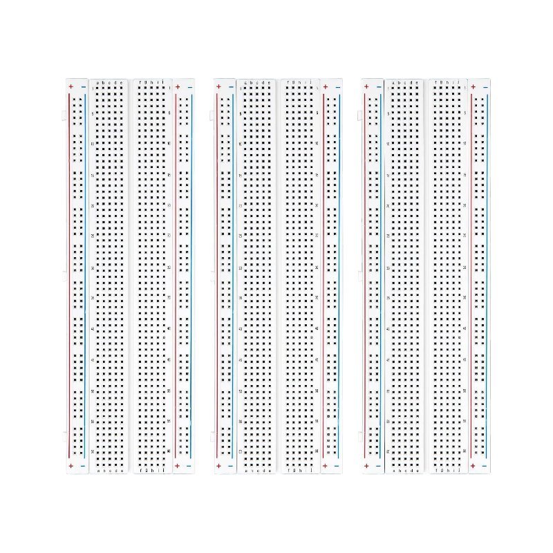
When I replace a board I buy them in multiples, because the second-best debugging move in electronics is swapping a suspect part for a known-good one, and you can’t do that with a single board. ELEGOO’s three-pack is the one I keep reaching for: standard 830-point layout, clips that still grip after heavy use, printed rail markings you can actually read, and adhesive backing so you can stick one down to a project base instead of having it slide around mid-test.
Three full-size 830-point boards with 630-point main grids, four power rails each, side clips for ganging boards together, and adhesive backs. Rated for 21–26 AWG wire. Buying three at once means you always have a known-good board to swap in when you suspect the one in front of you.
Check Price on Amazon →6. You never tied the grounds together
The moment your project has two power sources — the Arduino on USB and a battery pack driving a motor, say — you need a wire connecting their grounds. This is not optional and it is not obvious, because both halves of the circuit have power and look alive.
Voltage is a difference between two points, not an absolute quantity. If your Arduino and your battery pack don’t share a common reference point, then “5V” on one side and “0V” on the other aren’t measured against the same zero, and a signal pin sending HIGH is sending it into a void. Run a jumper from the Arduino’s GND to the negative rail your other supply uses, and half of the strangest bugs in beginner robotics disappear. If you’re mixing a 5V board with a 3.3V device on top of that, the 5V vs. 3.3V logic levels guide covers the other half of that problem.
Stop staring at it and start bisecting
Once you’ve been through the list above and it still won’t go, quit looking at the whole board at once. Tear it down to power only and confirm you actually have voltage on both rails where you think you do. Then add back one section at a time — one component, one wire — and test after each. It feels slower than scanning the finished circuit for the mistake, and it is dramatically faster in practice, because the moment it breaks you know exactly which connection did it.
The mental shift that matters here: the breadboard is a component, and components fail. Beginners treat the board as fixed infrastructure and assume the error must be in the code or the part, which is why these bugs eat entire afternoons. Treat the board as suspect number one and most of them collapse in minutes. If you want the ground-up version of how these connections are laid out in the first place, our Breadboards 101 guide walks through it.