Ask a beginner what makes a robot work and you will hear about the microcontroller, the sensors, maybe the motor driver. Almost nobody says “the piece of plastic everything is bolted to.” Then the robot gets built, and it pulls to the left, or it tips forward every time it stops, or the ultrasonic sensor reads garbage because the whole deck resonates like a tuning fork at half throttle. All of those are chassis problems wearing a software costume, and no amount of tuning your code will fix them.
The chassis is doing three jobs at once: it holds the wheels in a fixed geometric relationship to each other, it decides where the robot’s weight sits relative to those wheels, and it gives you somewhere to bolt everything else. Get those three right and a $14 acrylic plate outperforms a beautiful machined frame with the battery in the wrong place.
Two Wheels and a Caster: Why That Layout Won
Nearly every beginner chassis is a differential drive robot: two independently driven wheels on a shared axle line, plus a free-spinning caster or ball bearing holding up the other end. “Differential” just means steering comes from the difference between the two wheel speeds rather than from any steering mechanism. Both wheels forward at the same speed and you drive straight. Left wheel slower and you arc left. Run them in opposite directions and the robot spins in place around the midpoint of the axle, a zero-radius turn that a car with a steering rack physically cannot do.
That last property is why this layout dominates hobby robotics. A line follower that overshoots its line needs to pivot back onto it in a corridor no wider than itself. A maze solver needs 90-degree turns at a dead end. Differential drive gives you both for free, with no extra hardware, and the steering logic reduces to two numbers you already have to compute anyway. The caster is not a design compromise so much as the cheapest possible third contact point: it carries load and does nothing else. Its one requirement is that it swivel freely, which is why a gritty caster is a genuinely common cause of a robot that mysteriously veers.
Center of Gravity Is the Thing That Bites People
Here is the rule worth memorizing: the battery goes over the drive axle, as low as it will sit.
The battery pack is usually the heaviest single object on a small robot, often heavier than everything else combined. Traction is a function of how much weight is pressing the driven wheels into the floor, so weight sitting over the caster is weight actively working against you. Mount your four AA cells out at the front of the deck and you get a robot that spins its wheels on carpet, noses down under braking, and steers unpredictably because the caster is bearing load it was never meant to bear.
Low matters for a separate reason. A tall stack of boards and battery raises the center of gravity, and the higher it sits the more the whole robot pitches when the motors start and stop. That pitching shows up as noise in anything you have mounted up top: an ultrasonic sensor that suddenly reports a wall six inches closer, an accelerometer that cannot tell acceleration from tilt. Most acrylic chassis kits ship with the battery box designed to bolt to the underside of the deck rather than on top of it. That is not a packaging accident, and you should use it.
Wheelbase, Track Width, and Wheel Diameter
Three dimensions change how your robot behaves, and none of them are adjustable after you have drilled the holes.
Track width is the distance between the two drive wheels. A narrow track pivots fast but amplifies every small mismatch between your motors, so the robot feels twitchy and hard to drive straight. A wide track is stable and forgiving but needs more room to turn. Wheelbase is the distance from the drive axle to the caster, and a longer one damps out wobble at the cost of a lazier response. Wheel diameter is a gear ratio hiding in plain sight: bigger wheels cover more ground per revolution, so the same motor gives you a faster but weaker robot. Swapping 65 mm wheels for 42 mm ones is a real torque increase, which is worth knowing when your robot cannot get up the lip of a rug.
Beginners tend to fixate on speed. Do not. A slow robot gives your sensors time to actually return a reading before the situation changes, and almost every first project fails from being too fast rather than too slow.
What “1:48” and “200 RPM” Mean on a Motor Spec
Chassis kits ship with yellow TT gear motors, and the spec line is always the same: 3 to 6 V, 1:48 reduction, roughly 200 RPM. Decoded: the bare motor inside spins fast and weak, and a plastic gearbox trades 48 turns of the motor for 1 turn of the output shaft, converting that speed into usable torque. The RPM figure is measured at 6 V with nothing attached. At 3 V the same motor gives you about 90 RPM, and under actual load with a robot’s weight on it, expect meaningfully less than the number on the box.
That voltage range also explains a common wiring mistake. These motors want 3-6 V of raw battery power through a driver; they do not run off an Arduino pin, which is a control signal rated for about 20 mA. If that distinction is new, read how motor drivers actually work before you wire anything, and servos vs. DC motors vs. stepper motors if you are still deciding what kind of motor your build wants.
One more detail that matters for chassis choice: most TT motors are dual shaft, meaning a second stub of shaft pokes out the back of the gearbox. That stub exists so you can slot an encoder disc onto it and measure how fast the wheel is really turning. Kits that include those discs are quietly more capable than kits that do not.
Acrylic or Aluminum
Acrylic is the default for good reasons: it is cheap, light, laser-cut with a grid of mounting slots, and easy to drill when you need a hole the manufacturer did not anticipate. Its weaknesses are that it flexes under a heavy build and it cracks rather than bends if you overtighten a screw or drop the robot. Aluminum is stiffer, survives being knocked around, and holds up outdoors where an acrylic deck will eventually crack at a stress point. It also costs twice as much and is a nuisance to modify without proper tools.
For a first robot living on a desk and a hallway floor, acrylic. Move to aluminum when you are running four motors, carrying a bigger battery, or driving on anything rougher than flooring.
What to Actually Buy
This post contains affiliate links. If you buy through them, this site earns a commission at no extra cost to you.
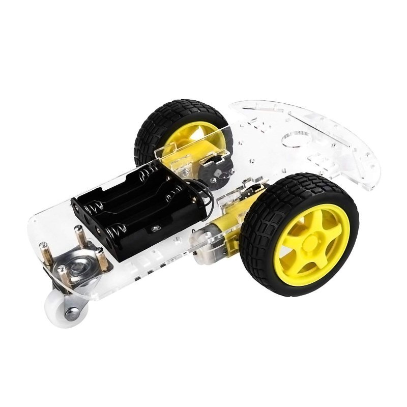
For a first build, buy the boring one. A basic 2WD acrylic kit gets you the deck, two TT gear motors with brackets, two wheels, a caster, the battery box, and the standoffs and screws to hold it together, which is everything structural you need to get an Arduino and an L298N bolted down and driving. The version I would point people at is the one that also throws in encoder discs, because that costs nothing extra and leaves the door open to closed-loop speed control later.
Acrylic deck pre-slotted for an Uno and an L298N, two 1:48 TT gear motors, wheels, caster, battery box, and encoder discs. Around $14, and there is very little reason to spend more on your first frame.
Check Price on Amazon →attachInterrupt() to count pulses, then divide by the number of slots on your disc (usually 20) to get wheel revolutions. Print it to the Serial Monitor and drive the robot by hand across carpet and tile — you will watch the two wheels report different speeds at identical motor commands, which is exactly why robots drift.
If you already know the robot is going outside, onto grass or gravel or a driveway, skip the acrylic stage. Four driven wheels roughly double your available traction and remove the caster entirely, which is the single most fragile part of a 2WD robot on rough ground. The tradeoff is that four motors draw more current, turning is now skid-steer rather than a clean pivot, and you will want a proper battery pack rather than a AA box.
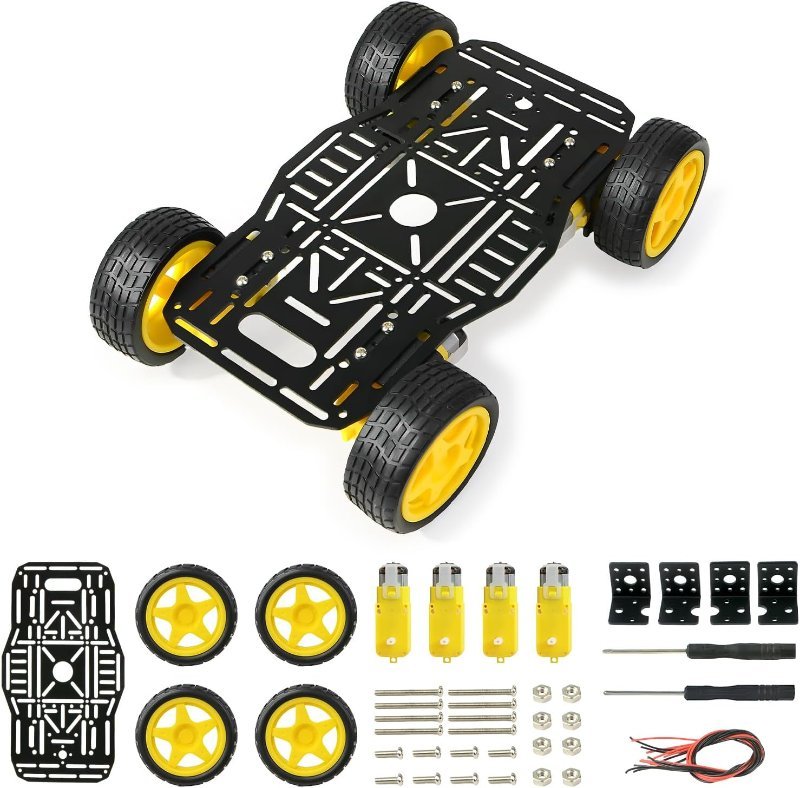
Aluminum frame, four TT motors, four rubber tires, and a slot pattern that takes an Uno or a Raspberry Pi. Around $33. Buy this when the acrylic deck has started flexing or you are driving on anything that is not a floor.
Check Price on Amazon →Assembly Order That Saves You Rework
Mount the motors first, and check that the two shafts are parallel with a straight edge before you tighten anything. Misaligned motors make a robot that drifts even when both wheels are commanded identically, and it is the kind of fault you will spend an evening blaming on your code. Then place the battery over the axle, underslung if the kit allows it. Boards go on last, in the space that is left, because boards are light and their position barely affects handling — whereas the motors and battery determine everything.
Leave the acrylic’s protective paper film on until the very end. It peels off cleanly, it stops you scratching the deck while you are wrestling screws, and at least half of the “my chassis arrived cloudy” complaints on these kits are someone who never realized the film was there.
Once it drives, give it a job. A line-following robot is the standard first build on exactly this hardware, and it will expose every chassis decision you just made — a high center of gravity, a sticky caster, or mismatched motors all show up immediately as a robot that cannot hold a line.