A reaction-time game is the project I hand people who have finished blinking an LED and want to know what a microcontroller is actually for. It needs almost nothing — one LED, one button, about forty lines of code — and yet it does something your laptop is genuinely bad at: measure one event, once, to the millisecond, with no operating system deciding when it feels like paying attention.
It is also the first project most people build where the code is the interesting part rather than the wiring. There is no sensor to calibrate and no motor to power. Everything hard about it happens in the timing logic, which makes it a near-perfect teaching project. Here is the whole build, including the part of millis() that almost no tutorial mentions.
What the game actually does
Four steps, in a loop. The board waits a random amount of time so you cannot anticipate it. It turns on an LED. It records the exact moment the LED came on. Then it sits in a tight loop watching the button, and the instant the button goes down it subtracts the two timestamps. The difference, in milliseconds, is your reaction time.
That is the entire game. Everything else — a display, a buzzer, a high-score table, a second player — is decoration on top of those four steps. Build the four steps first with the Serial Monitor as your only output, confirm the numbers look sane, and only then add hardware.
Why millis() is the right tool — and the odd thing about it
millis() returns how many milliseconds the board has been running the current sketch. Its return type is unsigned long, which matters: Arduino’s own documentation warns that doing arithmetic on it with a smaller type like int causes logic errors, and that even a signed long can break because its maximum value is half that of the unsigned version. Declare your timestamps unsigned long and the problem disappears.
Now the part that surprises people. On 16 MHz AVR boards — which is to say the Uno and the Nano — millis() does not tick once per millisecond. It is incremented every 1.024 milliseconds, and then incremented by 2 instead of 1 every 41 or 42 ticks to pull it back into sync. The net effect is that some millis() values are simply skipped. Your counter is correct over any meaningful span, but it is not a clean one-per-millisecond march, and Arduino’s docs explicitly suggest micros() when you need accurate timing over short intervals.
Does that matter for a reaction game? Not really, and it is worth being honest about why: human reaction times land in the hundreds of milliseconds, so a possible one-millisecond skip is noise against a 250 ms measurement. But it is a good thing to know before you build something where it does matter. If you ever want sub-millisecond resolution, micros() is there — just remember it wraps back to zero after roughly 70 minutes, where millis() gives you about 50 days before it rolls over.
Making the wait genuinely unpredictable
This is where first attempts fall apart. random() on an Arduino is a pseudo-random generator: the sequence is very long and looks random, but it is always the same sequence. Upload your sketch, play five rounds, press reset, and you will get the identical five delays in the identical order. After two resets a determined player can simply count.
The fix is randomSeed(), which starts the generator at an arbitrary point in that sequence. You need something unpredictable to feed it, and the standard trick — the one in Arduino’s own reference — is analogRead() on a pin with nothing connected to it. A floating analog input drifts around on electrical noise, so reading it gives you a number nobody can predict. One caveat from the docs worth filing away: if the seed works out to 0, randomSeed() has no effect at all.
The parts you actually need
Strictly speaking: a board, one LED with a current-limiting resistor, and one momentary pushbutton. That is a $3 bill of materials if you already own an Arduino. The honest recommendation depends on which of those you are missing.
This post contains affiliate links. If you buy through them, this site earns a commission at no extra cost to you.
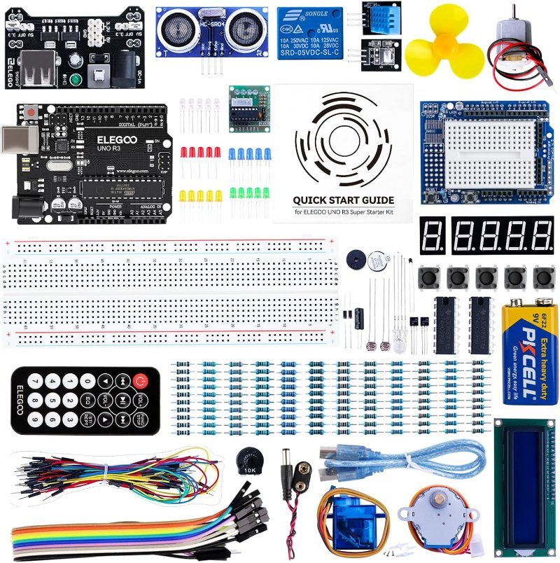
If you are starting from nothing, buy the parts in one box rather than four separate orders. A starter kit built around an UNO R3 gives you the board, the breadboard, assorted LEDs and resistors, tactile buttons, a 1602 LCD and a buzzer — every single component this project can use, including the optional upgrades below, for less than buying them individually. This is the version of the kit I keep pointing beginners at because the component selection is unusually sensible: fewer novelty modules, more of the passive parts you actually burn through.
Board, breadboard, LEDs, resistors, buttons, a 1602 LCD and a buzzer in one box — everything this build needs plus both upgrades, with a PDF tutorial thrown in.
Check Price on Amazon →Once the Serial Monitor version works, the first upgrade worth making is getting the number off your computer screen. A 16×2 character LCD with an I2C adapter soldered to the back costs a few dollars and turns the project into a standalone device you can hand to someone. The I2C part matters: instead of the six or more pins a bare 1602 needs, the adapter board reduces it to four wires — power, ground, SDA and SCL — which leaves the rest of your pins free. If the display comes up blank or the scanner sketch finds nothing, that is almost always an address or wiring issue rather than a dead module.
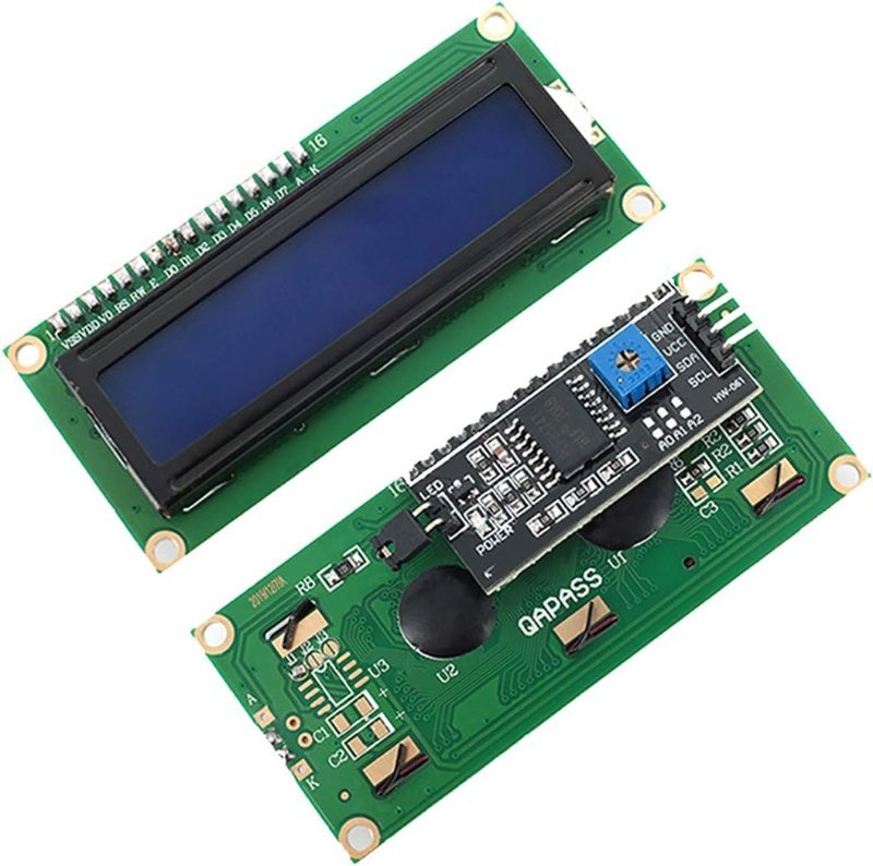
Four wires instead of six-plus, a blue backlight you can read across a room, and the LiquidCrystal_I2C library does the rest. Turns the sketch into a real gadget.
The second upgrade is the one that makes people actually want to play. A tactile pushbutton on a breadboard is fine for testing and terrible for a game — you end up poking delicately at a 6 mm square instead of slamming something. A 60 mm arcade button with a proper screw-terminal microswitch fixes that, and the microswitch is just a switch: wire its normally-open blade to your digital pin exactly like the breadboard button, INPUT_PULLUP and all. One thing to check before you buy: the lamp inside these buttons is often rated for 12 V, which is not something to hang off a 5 V Arduino pin. Drive the microswitch from the board and the lamp from its own supply, or ignore the lamp and use a separate indicator LED like the sketch below does.
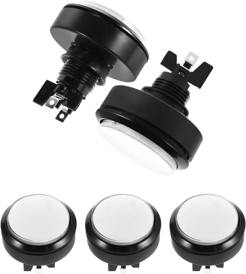
Satisfying to hit, screw terminals instead of fragile legs, and five of them means a two-player head-to-head version is one extra digital pin away.
Check Price on Amazon →digitalWrite(LED, HIGH) for a tone() call on a passive piezo buzzer and keep everything else identical — same random delay, same millis() subtraction. Then run twenty rounds of each and compare your averages. Most people are measurably faster to a beep than to a light, and you will have measured it on your own hardware rather than taken someone’s word for it.
The sketch
LED on pin 9, button between pin 7 and ground. Pin 9 is one of the Uno’s PWM-capable pins, so if you later want the LED to glow dimly while the game is idle and snap to full brightness as the cue, analogWrite() will do it — see how PWM fakes analog output for why that works on a digital pin.
const int LED    = 9;
const int BUTTON = 7;

unsigned long cueTime;
unsigned long reaction;

void setup() {
  Serial.begin(9600);
  pinMode(LED, OUTPUT);
  pinMode(BUTTON, INPUT_PULLUP);
  randomSeed(analogRead(A0));   // A0 left unconnected on purpose
}

void loop() {
  Serial.println("Get ready...");
  digitalWrite(LED, LOW);

  unsigned long wait  = random(2000, 5000);
  unsigned long start = millis();

  // Wait out the random delay, but watch for an early press
  while (millis() - start < wait) {
    if (digitalRead(BUTTON) == LOW) {
      Serial.println("Too early. Let go and try again.");
      waitForRelease();
      return;
    }
  }

  digitalWrite(LED, HIGH);      // the cue
  cueTime = millis();

  while (digitalRead(BUTTON) == HIGH) {
    if (millis() - cueTime > 3000) {
      Serial.println("Too slow. No reading.");
      digitalWrite(LED, LOW);
      return;
    }
  }

  reaction = millis() - cueTime;
  digitalWrite(LED, LOW);
  Serial.print("Reaction: ");
  Serial.print(reaction);
  Serial.println(" ms");
  waitForRelease();
}

void waitForRelease() {
  delay(25);                               // let the contacts settle
  while (digitalRead(BUTTON) == LOW) { }   // hold until the finger lifts
  delay(500);
}
Note that nothing here uses delay() to wait out the random interval. That is deliberate. delay() blocks — the board can do nothing else while it counts — which means a player could hold the button down through the entire wait and the sketch would never notice. Comparing millis() - start against the target instead lets the loop keep reading the button the whole time, which is how the early-press detection works at all.
Also note INPUT_PULLUP on the button pin. It switches on a resistor inside the chip that holds the pin at 5 V until your button connects it to ground, which is why the code tests for LOW rather than HIGH. Without it the pin floats and reads whatever it likes. If you are wiring this on an ESP32 or another 3.3 V board instead, the same logic applies at a different voltage — worth reading up on 5V vs. 3.3V logic levels before you mix parts.
Catching the player who jumps the gun
Two cheats need handling, and both are in the sketch above. The first is pressing before the cue, which the wait loop catches and reports as a foul. The second is subtler: holding the button down permanently, so that the instant the LED lights the pin is already LOW and the game reports an impossible 0 ms. That is what waitForRelease() is for — after every round the sketch refuses to continue until the pin goes back HIGH.
The delay(25) at the top of that function is a crude software debounce. Mechanical contacts do not close cleanly; they chatter for a few milliseconds, and a loop fast enough to time a reaction is more than fast enough to see that chatter as several separate presses. Twenty-five milliseconds of doing nothing lets the contacts settle. SparkFun’s own reaction timer uses exactly this pattern — a short delay followed by a wait-for-release loop — which is reassuring if you were wondering whether something this blunt is legitimate. It is, for a game. It would not be for a rotary encoder.
What your numbers will actually look like
Expect a few hundred milliseconds. SparkFun, who built essentially this project into an enclosure and left it sitting around their office, published screenshots of a 178 ms run and a 288 ms run, and reckoned the office average sat around 160 ms once the morning coffee had landed. Treat that as a hardware-nerd office’s informal benchmark rather than a published norm — they give no sample size or method — but it is a reasonable sanity check. If your sketch is reporting 40 ms, you are not superhuman; you have a held button or a missing release check.
One more honest caveat: you are not measuring pure neural latency. Your number includes however long the LED takes to become visibly bright, the microswitch travel, the polling loop, and any latency the display adds. None of that is large, but it means your Arduino score and your score on some browser reaction test are not directly comparable. Compare your readings against your own readings, which is the only comparison that was ever going to be meaningful anyway.
Build the four-step version tonight with a breadboard button and the Serial Monitor. It will take under an hour, and you will come away understanding non-blocking timing — the single most useful pattern in Arduino programming — better than any tutorial about it could teach you.