You’ll see “5V” and “3.3V” thrown around constantly in Arduino and robotics content — an Uno is 5V, an ESP32 is 3.3V, some sensors want one or the other, and occasionally a tutorial warns that wiring the wrong combination together “can damage your board.” This post exists so every other post on this site can link here instead of re-explaining it from scratch: what these numbers actually mean, why they exist, and what genuinely happens if you ignore them.
What “5V Logic” and “3.3V Logic” Actually Mean
A microcontroller’s digital pins don’t send information as smooth, continuously varying voltage — they send it as one of exactly two states, HIGH or LOW, and the chip’s job is to read a pin’s voltage and decide which state it represents. “5V logic” means the chip treats roughly 5 volts as HIGH and 0 volts as LOW; “3.3V logic” means it treats roughly 3.3 volts as HIGH instead. Both systems are just “on” and “off” — they only disagree about how many volts count as “on.”
The Arduino Uno and Nano use the ATmega328P chip, which runs its internal logic at 5V, so every pin on those boards speaks 5V logic. The ESP32 (and most other WiFi-capable boards, along with the Raspberry Pi) uses a chip that runs at 3.3V internally for power-efficiency and manufacturing reasons — running digital logic at a lower voltage uses meaningfully less power, which matters a lot for a chip that’s also running a radio. Neither voltage is “more correct” — they’re just two different design choices that happened to both become common.
Why Mixing Them Isn’t Automatically Fine
The direction you’re mixing them in matters, and it splits into two very different situations:
Feeding a 3.3V input with a 5V signal is the dangerous direction. A 3.3V chip’s pins are generally only rated to tolerate up to somewhere around 3.6V before damage — some chips have limited tolerance a bit above that, but it’s never a given, and it varies by chip and even by pin. Send that same pin 5V — which is what a straightforward wire from an Uno’s output would do — and you’re pushing roughly 1.5V past what the pin is built for. That doesn’t always destroy the pin instantly, but it stresses it every time it happens, and gradual damage or an outright dead GPIO pin are both realistic outcomes. This is the actual mechanism behind every “don’t connect a 5V board directly to a 3.3V board” warning you’ll read.
Feeding a 5V input with a 3.3V signal usually just doesn’t work reliably — it’s not damaging, just broken. A 5V chip typically needs a pin to reach somewhere around 3.0-4.0V (specifics vary by chip) before it reliably reads HIGH rather than an ambiguous or LOW state. A 3.3V output sits right at the edge of that threshold, so it might work on one board and fail intermittently on another, which is arguably more frustrating to debug than a clean failure, since it can look like a wiring or code problem instead of a voltage mismatch.
Where This Actually Comes Up in a Real Project
Most beginner projects never hit this at all — if you’re using an Uno with Uno-era sensors (the HC-SR04, a DHT22, a basic servo), everything in the circuit is already 5V and there’s nothing to reconcile. It becomes relevant the moment you introduce a 3.3V board into a project, most commonly when swapping an Uno for an ESP32 partway through a build to add WiFi. At that point, check the datasheet or listing for every sensor and module in the circuit before wiring it to the ESP32’s pins — plenty of common sensor breakout boards (many I2C sensors, some ultrasonic modules) are explicitly built to run on either voltage and say so; others are 5V-only and need to be kept off the ESP32’s direct pins.
The Fix When You Do Need to Mix Them
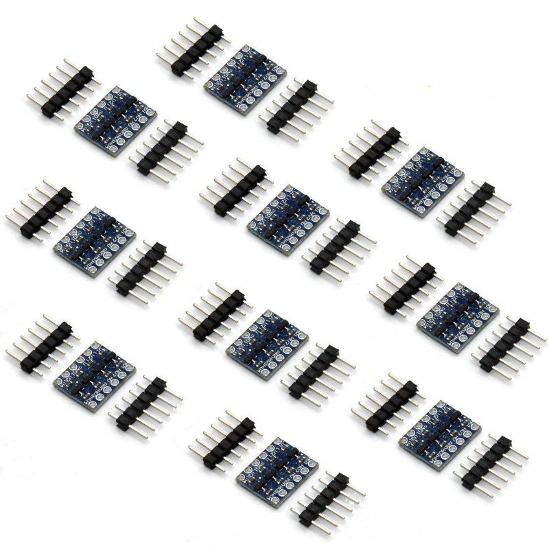
A logic level converter (also called a level shifter) sits between the two devices and translates the signal in both directions — 5V down to 3.3V going one way, 3.3V up to a clean 5V going the other. Bidirectional I2C-style level converters are inexpensive and handle the vast majority of hobbyist cases (I2C sensors, SPI devices, simple digital signals). Wire the 5V side to your 5V board, the 3.3V side to your 3.3V board, and the shared ground between both — the converter handles the translation in the middle.
This post contains affiliate links. If you buy through them, this site earns a commission at no extra cost to you.
Bidirectional, handles 4 signal lines per board, and a 10-pack means you’re never without one mid-project. The standard fix for mixing 5V and 3.3V devices in the same circuit.
Check Price on Amazon →digitalRead(). Watch a 5V signal safely become a 3.3V one in real time, instead of just taking our word for it.
The Short Version
5V and 3.3V are just two different voltage thresholds different chips use to mean “on.” All-Uno or all-ESP32 projects never need to think about this. The moment a project mixes 5V and 3.3V boards, check every sensor’s rated voltage before wiring it in, and reach for a logic level converter any time a 5V output would otherwise feed directly into a 3.3V input.