Your board already has an LED built in, wired to pin 13, blinking away the moment you run the example sketch. So why does every single tutorial insist you wire up a separate external LED as your actual “first project”? Because the built-in one lets you skip the two things that make this genuinely your first project: wiring a real circuit, and understanding what the code is doing to control it — not just watching it happen.
What a GPIO Pin Actually Is
“GPIO” stands for General Purpose Input/Output — it just means a pin the chip can be told, in software, to either read a voltage (input) or set a voltage (output). Set as an output and told to go HIGH, an Uno pin puts out roughly 5V; told to go LOW, it drops to 0V. That’s the entire mechanism behind every blinking-LED project: the chip is just switching a pin between two voltage states on a schedule your code defines.
Why the Onboard LED Isn’t Enough — and Why You Need a Resistor
The onboard LED already has its current-limiting resistor built onto the board, invisible to you. Wire an external LED straight to a pin with no resistor and you’ll very likely burn it out, because an LED’s resistance is low enough that, without something limiting the current, it draws far more than either the LED or the pin is rated for. A resistor in series with the LED limits that current to a safe level — a basic version of Ohm’s law (current = voltage ÷ resistance) is the entire reason a ~220-330Ω resistor between the pin and the LED is standard advice for a 5V board: it’s enough resistance to bring the current down into a safe range (typically under 20mA) without dimming the LED to nothing.
This post contains affiliate links. If you buy through them, this site earns a commission at no extra cost to you.
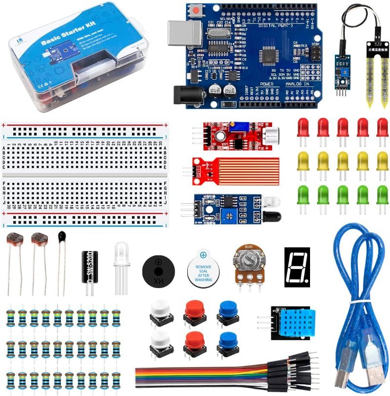
Comes with LEDs, a range of resistors, and a breadboard — everything this project needs beyond the board itself.
Check Price on Amazon →Wiring It
Run a wire from digital pin 13 to one leg of a ~220Ω resistor, the resistor’s other leg to the LED’s longer leg (the anode, the positive side), and the LED’s shorter leg (the cathode) to a GND pin on the board. LEDs only conduct current in one direction, so if it doesn’t light up, the first thing to try is flipping it around before assuming anything else is wrong.
The Code, and Why Each Line Is There
In setup(), pinMode(13, OUTPUT); tells the chip that pin 13 will be used to send voltage out, not read it — GPIO pins default to a different, input-oriented state, so this line has to run once before the pin will behave as an output at all. In loop() (which repeats forever after setup finishes), digitalWrite(13, HIGH); sets the pin to 5V, turning the LED on; delay(1000); pauses execution for 1000 milliseconds, doing nothing else during that time; digitalWrite(13, LOW); drops the pin back to 0V, turning the LED off; and a second delay(1000); holds that off-state for another second before loop() repeats from the top. Change either delay value and you’re directly changing how long the LED stays on or off — which is the whole project, made explicit instead of hidden inside a pre-written example.