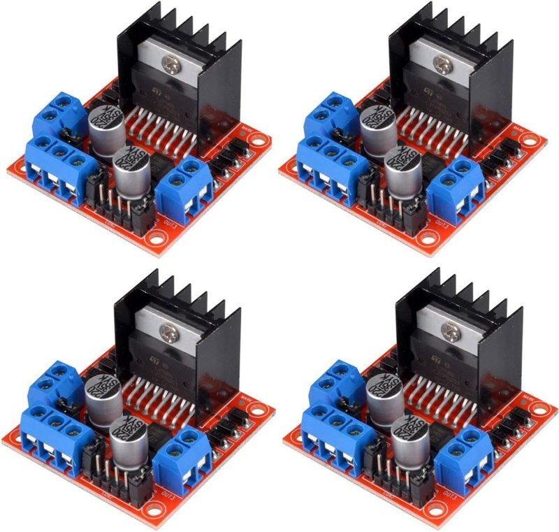
If you have ever bought a robot kit, you already own an L298N. It is the blue-and-black board with the oversized aluminum heat sink bolted to the middle of it, and it has been the default motor driver in beginner robotics for the better part of two decades. It is also, by any modern engineering standard, a bad chip.
Both of those things are true at once, and that tension is the whole review. The L298N is worth buying — I keep a stack of them on the shelf — but you should know exactly what you are trading away when you reach for one, because most tutorials never tell you.
What the board actually does
An Arduino pin can source about 20 milliamps safely. A cheap yellow gearmotor wants 200 to 600. You cannot wire one to the other, and that gap is the entire reason motor drivers exist — the driver takes a tiny logic-level signal and uses it to gate a much larger current from a separate power supply. We covered that idea in general terms in how motor drivers actually work; this post is about the specific board.
The L298N gives you two independent H-bridges. An H-bridge is four switches arranged in a square around the motor: close the top-left and bottom-right pair and current runs one way, close the other diagonal pair and it runs the opposite way. That is all "reverse" means electrically. Two bridges means two DC motors, or one bipolar stepper motor, from a single board.
The six pins you actually touch
Per motor, you get three control pins. IN1 and IN2 set direction: one HIGH and one LOW spins the motor, flipping which is which reverses it, and both LOW coasts to a stop. ENA turns that channel on and off — and if you feed it a PWM signal instead of a plain HIGH, it becomes your throttle.
PWM, short for pulse-width modulation, is the trick Arduino uses to fake an analog output: it switches the pin fully on and fully off thousands of times a second and varies the ratio. analogWrite(enA, 128) means on half the time, and a motor — which has far too much physical inertia to follow a signal that fast — just spins at roughly half speed. Motor B gets the identical treatment on IN3, IN4 and ENB.
One gotcha that trips up nearly everyone: the boards ship with plastic jumpers shorting ENA and ENB to 5V. That is why your motors run at full blast and ignore every analogWrite() you send. Pull those two jumpers off before you wire anything to ENA/ENB, or you will spend an hour debugging code that was never the problem.
The voltage drop is the real story
Here is the part that separates the L298N from anything designed in this century. Its output stage uses bipolar Darlington transistor pairs, not MOSFETs, and Darlingtons burn a fixed chunk of voltage just by conducting. The datasheet puts the drop at roughly 1.8V to 3.2V at around 1 amp, climbing toward 5V as you approach the chip’s 2A-per-channel limit.
Translate that: feed the board 12V and your motors see about 10V. Feed it 7.4V from a small lithium pack, which is what most desk-sized robots run, and your motors see something closer to 5V. That missing voltage does not vanish — it turns into heat inside the chip, which is precisely why the board needs that comically large heat sink in the first place. Overall efficiency lands somewhere in the 40–70% range depending on load.
For a line follower crawling across your kitchen floor on a wall wart, nobody cares. For a battery-powered robot where runtime is the whole point, you are throwing away a third of your pack to warm up a heat sink.
The 5V jumper that kills boards
Next to the screw terminals is a third jumper, and this one has real consequences. The module carries an onboard 78M05 linear regulator that derives 5V from your motor supply. With the jumper installed and a supply of 12V or less, the 5V pin becomes an output — handy, since it can power an Arduino directly off the same battery.
Go above 12V with that jumper still on and you cook the regulator. Above 12V you pull the jumper and the 5V pin flips to being an input, which you must then feed from a separate 5V source, because the L298N’s logic side still needs it. Getting this backwards is one of the most common ways a working robot suddenly stops working — it is on our motor troubleshooting checklist for exactly that reason.
Worth noting: the logic inputs are happy with 5V signals from an Uno and generally tolerate 3.3V from an ESP32 as well, though margins get thin. If that distinction is new to you, read 5V vs. 3.3V logic levels before wiring an ESP32 to one.
Which one to buy
This post contains affiliate links. If you buy through them, this site earns a commission at no extra cost to you.
There is no meaningful design variation between L298N modules — they are all the same reference circuit from the same handful of factories, and the only real differences are solder quality and how many you get. So buy in bulk and stop thinking about it. HiLetgo’s four-pack is the one I keep restocking: the terminal blocks are properly soldered, the heat sink is actually attached rather than resting there, and at four boards to a pack you can afford to destroy one learning the 12V jumper lesson the hard way.
Two channels, 2A each, 5–35V motor supply, onboard 5V regulator. Clean solder work and enough spares that a mistake costs you nothing.
Check Price on Amazon →analogWrite(enA, 255). The gap between those two readings is the voltage your heat sink is converting into warm air — and watching it widen as you load the motor down with your thumb makes the whole Darlington problem click in a way no datasheet table does.
When to skip it entirely
If your robot runs on batteries and you care how long it lasts, the modern answer is the TB6612FNG. Toshiba’s chip swaps Darlington pairs for MOSFETs, which drops the on-state loss to roughly 0.2–0.5V instead of 2–4V. Efficiency lands north of 90%, the board is a fraction of the size, and it needs no heat sink at all because there is barely any waste heat to shed.
The trade is current headroom: 1.2A continuous per channel, 3.2A peak, against the L298N’s 2A. For the small gearmotors in a chassis kit that is plenty. For something chunkier, the L298N still wins on raw capability. The control interface is nearly identical — two direction pins plus a PWM pin per motor — so porting existing code over is a fifteen-minute job.
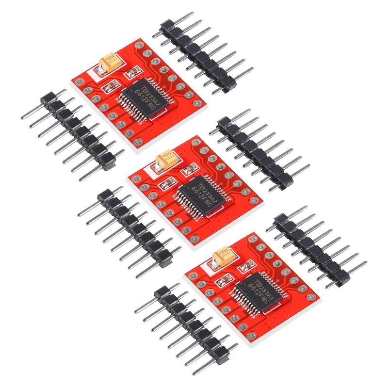
MOSFET output stage, ~0.5V drop, 1.2A continuous and 3.2A peak per channel. Half the size of an L298N and no heat sink required.
Check Price on Amazon →The verdict
Buy the L298N. Not because it is good, but because every tutorial, every wiring diagram, and every kit you will encounter in your first year assumes you have one, and learning on the part the documentation was written for is worth more than a few points of efficiency. It is the part that teaches you what an H-bridge is.
Then, once your robot works and you find yourself annoyed that it dies after twenty minutes, buy the TB6612FNG and feel the difference. That sequence — understand the obvious thing, then upgrade once you can articulate why — beats starting with the better part and never knowing what problem it solved. If you are still deciding what kind of motor belongs on the other end of the board, start with steppers vs. servos vs. DC motors.