Every Arduino tutorial tells you pin 13 is digital and A0 is analog, then moves on as if that settles it. It doesn’t. The difference between those two rows of headers isn’t a labeling convention — it’s two completely different circuits inside the chip looking at the same kind of wire and asking different questions of it. Confusing the two is behind a large share of “my sensor reads garbage” forum posts.
A Pin Is Just a Wire With an Opinion
Physically, every pin on an Arduino Uno is the same thing: a copper trace running to a leg on the ATmega328P microcontroller. What makes a pin “digital” or “analog” is which circuit inside that chip is listening. Digital pins feed a comparator that answers exactly one question — is this voltage above or below my threshold? Analog pins get routed through a shared analog-to-digital converter (an ADC, the circuit that turns a continuous voltage into a number) which answers a slower, more expensive question: on a scale of 0 to 1023, how high is this voltage?
That’s the entire distinction. Same copper, different interpreter.
Digital Pins: HIGH, LOW, and the Gray Zone Nobody Warns You About
An Uno R3 has 14 digital I/O pins, D0 through D13. digitalRead() on any of them returns one of exactly two values, HIGH or LOW, and the chip picks by comparing against thresholds defined as fractions of the supply voltage. On a 5V ATmega328P, roughly anything above 0.6 × Vcc (about 3.0V) reads HIGH, and anything below roughly 0.3 × Vcc (about 1.5V) reads LOW.
Notice what’s missing: everything between 1.5V and 3.0V. That band is undefined. Feed a pin 2.2V and the chip will return something — it just won’t reliably return the same thing twice. This is also the reason a 3.3V sensor’s HIGH usually reads fine on a 5V Uno while the reverse direction is the one that damages hardware; if that’s the wall you’re hitting, our 5V vs. 3.3V logic levels explainer covers it in full.
The other classic digital-pin trap is the floating input. A pin set to INPUT with nothing actively driving it does not sit politely at 0V — it drifts, picking up ambient electrical noise from your hand, your desk, and the mains wiring in the wall, and digitalRead() flickers between HIGH and LOW at random. The fix is pinMode(pin, INPUT_PULLUP), which switches on an internal resistor (roughly 20–50kΩ) tying the pin up to 5V. The pin now idles HIGH and your button only has to pull it to ground. Your logic inverts as a result — pressed means LOW — which catches out a lot of first-time button code.
Analog Pins Don’t Measure Voltage. They Rank It.
The Uno R3’s six analog inputs (A0–A5) share a 10-bit ADC. Ten bits means 1024 possible outputs, 0 through 1023, spread across a reference range that defaults to 0–5V. Each step is therefore about 4.9 millivolts. An analogRead(A0) of 512 does not mean “2.5 volts” — it means “about halfway to the reference,” and the reference is whatever your 5V rail is actually doing at that instant, which on USB power is often closer to 4.7V. Real measurement work needs analogReference() and the AREF pin; most projects can ignore that.
The ADC is also slow by microcontroller standards. One analogRead() takes about 100 microseconds, which caps you at roughly 10,000 readings per second. That’s generous for a temperature sensor and nowhere near enough for audio without dropping to register-level tricks. And because a single ADC is multiplexed across all six pins, reading six inputs costs six times as long — those pins are sampled one after another, never simultaneously.
The cheapest way to build intuition here is a potentiometer: a knob that acts as an adjustable voltage divider. Outer legs to 5V and ground, middle wiper to A0, then print analogRead(A0) to the Serial Monitor. Turning the knob walks that number smoothly from 0 to 1023, and “analog” stops being an abstraction about ten seconds later.
This post contains affiliate links. If you buy through them, this site earns a commission at no extra cost to you.
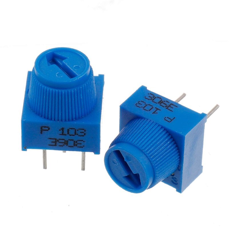
Breadboard-friendly 3-pin trimpots with knobs — the standard part for a first analog input experiment, and cheap enough that a ten-pack costs less than one panel-mount pot.
Check Price on Amazon →The Trap: analogWrite() Is Not Analog Output
This is the naming crime at the center of the whole topic. analogRead() really does read an analog voltage. analogWrite() does not write one. On an Uno R3 it produces PWM — pulse width modulation, a square wave snapping between 0V and 5V hundreds of times a second, varying only what fraction of each cycle is spent HIGH. analogWrite(pin, 128) gives you a 50% duty cycle: still fully on and fully off, just on half the time.
For an LED or a motor that’s indistinguishable from a real voltage change, because your eye and the motor’s inertia both average it out. For anything that actually cares about instantaneous voltage — an op-amp input, a control-voltage jack, an analog panel meter — it’s a stream of pulses, and you’ll need an RC filter or a real DAC. Two more details people trip over: analogWrite() only works on the six PWM-capable digital pins (3, 5, 6, 9, 10, and 11 on an Uno), not on A0–A5, and its argument range is 0–255, not 0–1023. Default PWM frequency is about 490 Hz on most of those pins, and about 980 Hz on pins 5 and 6.
The Uno R4 is the exception worth knowing. Its ADC can be raised to 12- or 14-bit resolution with analogReadResolution(), and A0 doubles as a true 12-bit DAC — an actual steady analog output voltage rather than a pulse train. If the paragraph above describes a problem your project has, that’s the concrete reason to buy an R4 instead of an R3.
Analog Pins Make Fine Digital Pins (The Reverse Isn’t True)
A0 through A5 are also digital pins 14 through 19. pinMode(A0, OUTPUT) followed by digitalWrite(A0, HIGH) works exactly as you’d hope, and digitalRead(A0) is a perfectly good way to read a button. If you run out of digital pins while sitting on unused analog ones, take them.
Going the other direction fails on an R3, because D2 has no wire to the ADC. Worse, it fails quietly: analogRead(2) compiles and runs, but the argument is read as an analog channel number, so you silently get A2 instead of an error. That one has eaten entire evenings.
What to Buy to Actually Feel the Difference
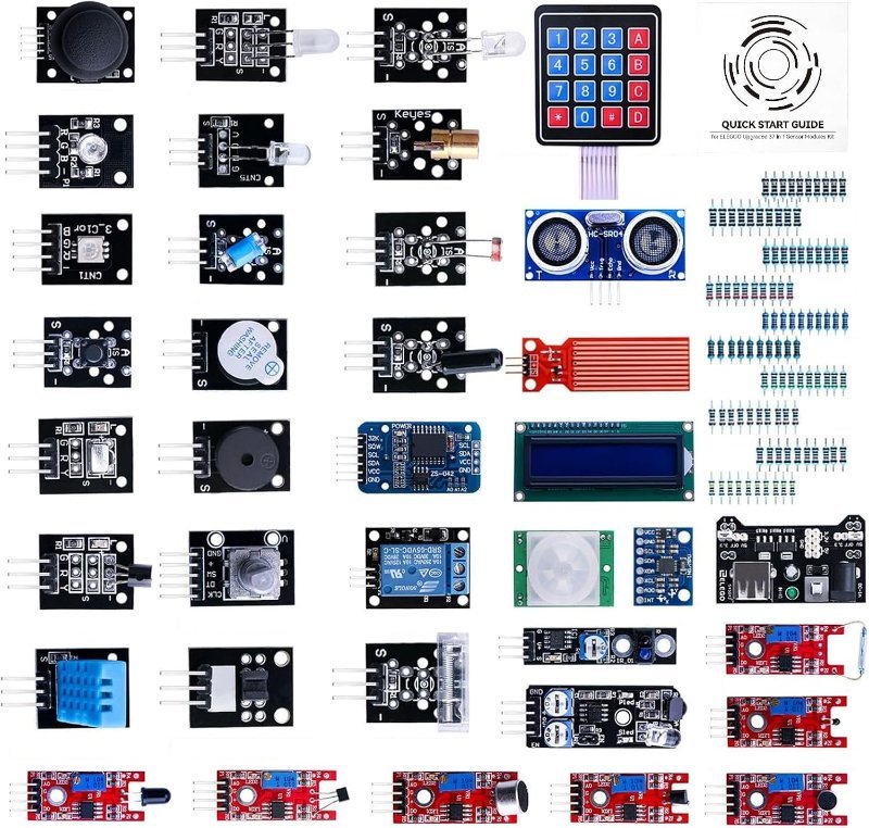
You can read all of the above and retain none of it. What makes it stick is having both kinds of sensor on one breadboard and watching them behave differently in the same loop — a tilt switch that only ever says HIGH or LOW sitting next to a photoresistor whose value slides continuously as your hand passes over it. A sensor module assortment is the efficient way there, since it hands you a dozen of each type for roughly what three individual modules cost.
A spread of both pin types in one box: photoresistor, temperature and sound modules on the analog side, tilt switches, reed switches, IR receivers and buttons on the digital side. Everything is broken out onto a small board with header pins, so you’re wiring three jumpers instead of building a divider from scratch — which is the point when the thing you’re studying is the pin, not the sensor.
Check Price on Amazon →analogRead(A0) and digitalRead(2) to the Serial Monitor in the same loop. Tip the board and the digital value jumps straight between 0 and 1 with nothing in between; wave your hand over the photoresistor and the analog value slides through hundreds of intermediate steps. Then put a multimeter across A0 and ground and check that the measured voltage tracks the count at roughly 4.9 mV per step — that’s the ADC’s math made visible.
The Short Version
- Digital pins answer “above or below the threshold?” On a 5V board that boundary sits near 3.0V for HIGH and 1.5V for LOW, with an unreliable gray zone between.
- Analog pins answer “where in a 0–1023 range?” — about 4.9 mV per step, about 100 µs per read, one ADC shared across all six inputs.
analogWrite()is PWM, not analog, and it lives on digital pins 3, 5, 6, 9, 10, 11 with a 0–255 range.- A0–A5 double as digital pins 14–19. Digital pins cannot do the reverse.
- A floating input is noise, not zero.
INPUT_PULLUPis almost always what you want.
Get those five straight and a surprising number of “it works sometimes” bugs stop happening.