A home alarm is one of the few beginner Arduino projects that has to keep working while nobody is watching it. That constraint is exactly what makes it worth building. A blinking LED forgives sloppy wiring and a sketch that only behaved on the third upload; an alarm that sleeps through a door opening, or shrieks at the cat at 3 a.m., tells you immediately that something in your design was wrong.
Every alarm — from a $25 breadboard build to a professionally installed panel — splits into the same three jobs: sense something, decide whether it matters, then make noise about it. Keep those layers separate and the project stays comprehensible. Try to collapse all three into one sensor and one if statement and you end up with something that is either deaf or hysterical.
Layer one: the motion sensor that isn’t really a motion sensor
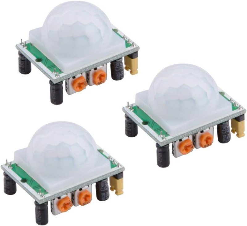
PIR stands for passive infrared, and the “passive” part is the interesting bit. An ultrasonic sensor emits a pulse and times the echo. A PIR emits nothing at all. It sits and watches infrared radiation — heat — landing on a pair of pyroelectric elements under that white plastic dome. The dome is a Fresnel lens, and its job is to carve the room into alternating zones. When a warm body crosses from one zone into the next, one element briefly sees more heat than its twin, and that difference is what trips the output.
Which means a PIR does not detect presence. It detects change. Sit perfectly still in front of one and it will eventually decide you are furniture. For an alarm that is fine — intruders move — but it is the wrong sensor if you ever wanted to know whether a room is occupied.
The HC-SR501 is the module nearly every tutorial on the internet is written against, and there is no good reason to deviate. It accepts 4.5V to 20V on VCC, so the Uno’s 5V rail is fine, and its OUT pin idles at 0V and swings to 3.3V TTL when triggered. That 3.3V figure is quietly useful: it reads as HIGH on a 5V Arduino and it is safe to feed straight into a 3.3V ESP32 with no level shifter in between. If that distinction is new to you, we broke it down in 5V vs. 3.3V logic levels.
Two orange potentiometers on the board set sensitivity (roughly 3 to 7 meters of range, across a cone of about 110°) and delay — how long OUT stays HIGH after a trigger, adjustable from about 5 seconds up to 5 minutes. There is also a small jumper marked H and L that picks the retriggering behavior. In H (repeatable) mode, continued motion keeps resetting the delay timer, so the output stays HIGH for as long as someone is moving. In L (non-repeatable) mode it goes HIGH once, waits out the delay, and drops LOW regardless. For an alarm you want H.
One gotcha catches everybody: the sensor needs roughly 30 to 60 seconds after power-up to stabilize before its output means anything. If your alarm screams the instant you plug it in, that is not a bug in your code. Build the warm-up in as a deliberate startup delay and print something to the Serial Monitor so you know it is happening on purpose.
This post contains affiliate links. If you buy through them, this site earns a commission at no extra cost to you.
Buy these in multiples. You will want one aimed down a hallway, one in whatever room you actually care about, and a spare to experiment with while the other two stay mounted. Adjustable sensitivity and delay pots on board, a 4.5–20V input range that tolerates whatever you feed it, and a 3.3V output that works with 5V and 3.3V boards alike.
Check Price on Amazon →Layer two: the sensor that knows a door opened
Motion sensing tells you something is moving inside a room. It does not tell you how it got in. For that, reach for the least glamorous component in this entire build: a magnetic reed switch.
A reed switch is two thin ferromagnetic contacts sealed inside a glass capsule. Bring a magnet close and the contacts snap together; take it away and they spring apart. No chip, no firmware, no power draw, essentially nothing to fail. The MC-38 packages this as two small plastic housings — switch in one, magnet in the other — that stick to a door frame and the door itself, about a centimeter apart.
The versions sold for alarm work are normally closed (NC), which sounds backwards until you think it through. Magnet present, door shut, circuit closed. Door swings open, magnet leaves, circuit breaks. A cut wire produces that same broken circuit, so a sensor that fails open reports tampering the same way it reports an intrusion. That is a deliberate design choice, not an accident.
Wiring is two wires and one line of code: one lead to GND, the other to a digital pin, and pinMode(DOOR_PIN, INPUT_PULLUP) in setup(). The Arduino’s internal pull-up resistor holds that pin at 5V whenever the switch is open, so a closed door reads LOW and an open door reads HIGH. Leave the pull-up out and the pin floats — it picks up ambient electrical noise from the air and reports essentially random values. That is the single most common reason a beginner’s door sensor “randomly triggers.”
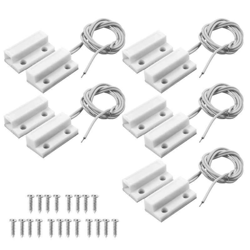
Five pairs covers every exterior door and a couple of windows with spares left over. Surface-mount housings with screw holes and adhesive backing, roughly 30cm of pigtail lead on each, and a normally-closed contact that reads correctly with nothing but INPUT_PULLUP. Nothing here can drift out of calibration, which is more than the motion sensor can say.
Layer three: making a noise nobody sleeps through
There are two kinds of buzzer, and buying the wrong one will quietly cost you an afternoon.
An active buzzer has an oscillator built into it. Apply DC voltage, get a fixed tone. digitalWrite(BUZZER, HIGH) and it beeps — that is the entire API. A passive buzzer has no oscillator. It is a bare piezo element that only vibrates when you feed it an alternating signal, which means generating the frequency is your job.
Take the passive one. Arduino’s built-in tone() function generates that square wave for you at anything from 31 Hz to roughly 65 kHz, so a rising-and-falling siren becomes a short for loop instead of a flat, easily-tuned-out beep. tone(BUZZER, freq) starts it, noTone(BUZZER) stops it, and sweeping freq from about 400 up to 1200 and back down produces the wail everyone’s brain files under “emergency.” An active buzzer physically cannot do this — it plays its one note no matter what frequency you ask for.
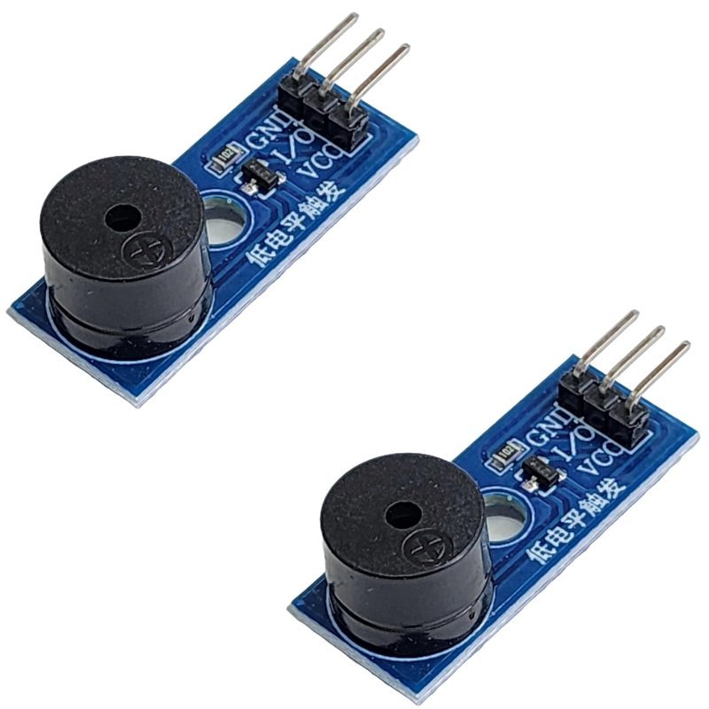
Board-mounted with header pins, so it drops onto a breadboard without you soldering leads to a bare piezo disc. Passive, which is the point: driven by tone() it can sweep pitch for a real siren, chirp once to confirm the system armed, and beep out an entry countdown — three different sounds from one part.
Layer four: arming and disarming without unplugging anything
An alarm you disarm by yanking the USB cable is a science project. A keypad is what turns it into something you would actually leave switched on.
A 4×4 membrane keypad gives you 16 keys across 8 digital pins, which sounds impossible until you see the wiring. The keys are not wired individually. They sit at the intersections of 4 row traces and 4 column traces, and pressing a key connects its row to its column. The Arduino works out which one by scanning: drive a single column LOW, check which row — if any — reads LOW in response, then move to the next column, cycling the whole grid hundreds of times per second. The row/column pair that lit up identifies the key.
You do not have to write any of that. The Keypad library by Mark Stanley and Alexander Brevig (Library Manager, search “Keypad”) runs the scan loop and hands you a plain character from getKey(). It uses the internal pull-ups too, so no external resistors.
The pin cost is real, though. Eight of the Uno’s 14 digital pins go to the keypad alone, before the PIR, the reed switch and the buzzer get theirs. If that gets tight, either move up to a Mega or buy the I2C version of the keypad, which trades those 8 pins for 2.
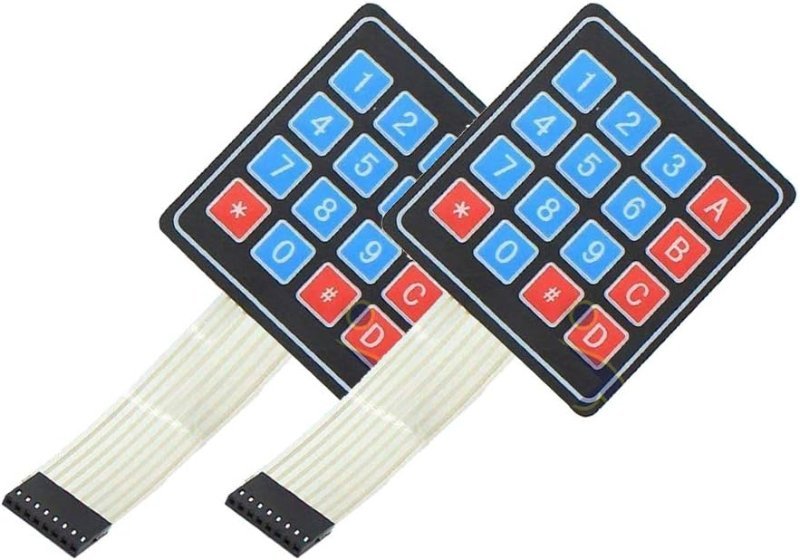
A flat adhesive-backed membrane with a ribbon terminating in 8 standard 0.1" header pins — straight into a breadboard, no adapter. Thin enough to stick to the inside of an enclosure and still press through. Two in the pack because the ribbon tail is the fragile part of these, and you will eventually crease one.
Check Price on Amazon →char buffer, compares it against a stored code with strcmp(), and flips an isArmed boolean. Then stop using the Serial Monitor as your readout and add a 16×2 I2C LCD — two data wires to A4 and A5 and the panel says ARMED or ENTER CODE by itself, instead of needing a laptop tethered to your front door.
The part no parts list teaches you: the state machine
Wiring is the easy half. An alarm has states — disarmed, armed, entry delay, triggered — and the mistake nearly everyone makes is trying to express that with nested if statements inside loop(). Declare an enum for the states and drive it with a single switch, and the whole thing collapses into something you can still read next month.
Two behaviors matter more than they sound. First, an entry delay: when a sensor trips while armed, do not fire the siren, start a 15–30 second countdown so you can key in the code after walking through your own front door. Second, latching: once the alarm fires it stays fired until somebody enters the code. If your siren stops the moment the door swings shut again, all an intruder has to do is close it behind them.
Where this build honestly stops
Be clear-eyed about what you have made. There is no cellular backup, no battery when the power cuts, no monitoring service, and a siren in your own living room only helps if somebody is around to hear it. This is an excellent learning project and a reasonable deterrent for a shed, a garage, a workshop or a dorm room. It is not a substitute for a monitored system on a house you are insuring.
The upgrade that closes most of that gap is not a better sensor — it is a better board. Swap the Uno for an ESP32 and the same sketch can push a notification to your phone the moment the reed switch opens, which turns a noise-maker into something that tells you what happened while you were out. Every component on this list runs happily on 3.3V logic as well as 5V, so nothing else in the build has to change.