Most “robotic arm” projects you find online are toys with a servo taped to a popsicle stick. The EEZYbotARM MK2 is not that. It’s a four-axis, fully 3D-printed arm designed by an Italian maker who goes by daGHIZmo, it has been remixed and rebuilt thousands of times since it landed on Thingiverse, and the whole thing runs on parts that cost less than a nice dinner. If you have a printer and an Arduino sitting in a drawer, this is the build that finally makes both of them feel worth owning.
What makes it worth writing about isn’t the printing. It’s the mechanism.
The Clever Part: All the Weight Stays at the Bottom
The obvious way to build a robot arm is the naive way: put a motor at the shoulder, then bolt another motor onto the end of that arm segment for the elbow, then another for the wrist. It works, and it’s how a lot of beginner arms are built. It’s also why those arms sag, overshoot, and shake.
The problem is that every motor you hang further out on the arm becomes weight the motors below it have to lift — and worse, it becomes inertia. Inertia is a body’s resistance to changing its motion, and it scales brutally with distance from the pivot. A servo mounted at the elbow doesn’t just add its 55 grams; it adds 55 grams at the end of a long lever, which the shoulder servo feels as a much larger load whenever it tries to start or stop. That’s why heavy-tipped arms wobble after they arrive at a position.
The EEZYbotARM sidesteps this with a parallel linkage — the same trick industrial palletizing robots use. All three main servos are bolted to the stationary base. The shoulder and elbow joints are driven remotely through rigid printed links that transmit motion out to the joints without the motor traveling along with it. The moving structure is nothing but plastic. The result is an arm that accelerates and stops crisply instead of flopping around, and a bonus geometric property: because the linkage keeps the gripper’s orientation fixed relative to the base, the end effector stays level as the arm moves through its reach. You don’t have to write any code to keep the gripper from tipping — the mechanism does it for you.
That’s a genuinely elegant piece of engineering to have sitting on your desk for the price of a spool of PLA.
What It Actually Takes to Build
Beyond the printed parts, the hardware list is short: a 606 bearing for the base rotation, a handful of 6 mm steel balls that ride in a printed race to carry the base’s thrust load, and an assortment of M3 and M4 screws and nuts. Three large servos handle base rotation, the shoulder link, and the elbow link; one small SG90 works the gripper.
The servo choice is the one place beginners get burned, so let’s be specific about it.
This post contains affiliate links. If you buy through them, this site earns a commission at no extra cost to you.
The Muscle: Metal-Gear Servos, Not Plastic Ones
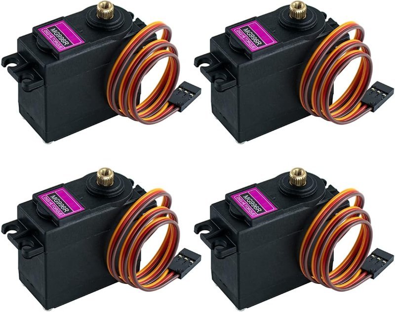
The original design calls for MG995 or MG946 servos; the MG996R is the current, widely stocked member of that same family and drops straight into the same mounting footprint. What matters is the word metal in “metal gear.” A 9-gram SG90 has a nylon gear train, and the first time your arm tries to lift something at full extension, you will hear a small crunch and one of those nylon teeth will be gone forever. The MG996R puts out roughly 11 kg‑cm of stall torque at 6 V through a metal gearset that survives being stalled. For an arm that will spend its life being asked to hold a position against gravity, that durability is the entire point. Buy them in a four-pack — you need three, and you will eventually want a spare.
11 kg-cm at 6V, metal gear train, standard 40×20×40 mm body that fits the EEZYbotARM mounts as-is. Three for the arm, one spare for when you inevitably strip something else.
Check Price on Amazon →analogRead() values to two servos, and you have a manual jog controller you’ll keep using long after the arm is assembled.
The Controller: Get the Servos Off the Arduino’s Timers
You can drive four servos straight from an Arduino Uno’s digital pins, and for a first test you should. But once you’re coordinating four axes into smooth motions, the Uno’s Servo library starts to feel cramped — it monopolizes hardware timers, and every servo update competes with whatever else your sketch is doing.
The fix is a PCA9685 board. It’s a dedicated 16-channel PWM generator that talks to the Arduino over I2C — a two-wire bus (SDA for data, SCL for clock) that lets one controller command many peripheral chips using just two pins total, no matter how many devices you chain on. PWM, or pulse width modulation, is how servos are told where to go in the first place: the board sends a pulse roughly every 20 ms, and the pulse’s width (about 1 ms to 2 ms) encodes the target angle. The PCA9685 generates all sixteen of those pulse trains in hardware at 12-bit resolution and holds them steady on its own, so your sketch just says “channel 2, this position” and goes back to doing something else. Your servo motion gets noticeably smoother, and you free up the Uno’s timers.
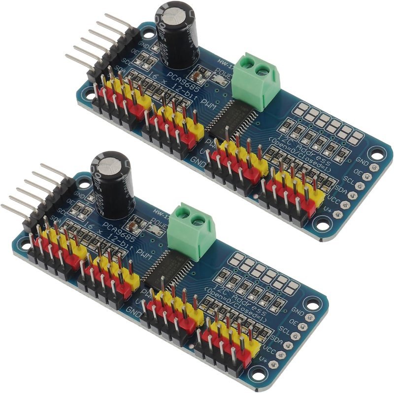
Two wires to the Arduino, sixteen independent servo channels out, 12-bit resolution generated in hardware. The single best upgrade for any multi-servo build.
Check Price on Amazon →One wiring note: the PCA9685 has a separate screw terminal for servo power, deliberately isolated from the logic supply. Use it. That separation is the whole reason the board is safe to build around, which brings us to the part that actually kills most first attempts.
The Part Everyone Skips: Real Power
Here is the failure mode, and it is nearly universal. You wire three MG996R servos to the Arduino’s 5 V pin, upload your sketch, the arm lurches, the board resets, and the serial connection drops. You assume your code is broken. Your code is fine.
An MG996R draws around 500 mA while running, but its stall current — what it pulls when it’s fighting a load it can’t move, including the instant it starts from rest — is about 2.5 A at 6 V. Three of them starting simultaneously can momentarily demand well over 7 A. The Arduino Uno’s onboard regulator is rated for a few hundred milliamps. It is not in the same universe as that number. The 5 V rail collapses, the microcontroller browns out, and the board reboots mid-motion.
The answer is an external supply feeding the servos directly, with only the ground line shared back to the Arduino so both sides agree on what zero volts means. Budget generously — a 5 V 10 A brick is not overkill for a four-servo arm, it’s the correct size. While you’re at it, solder a 1000 µF electrolytic capacitor across the servo power rails near the terminal block; it acts as a local reservoir that absorbs the inrush spike faster than the supply can respond, and it eliminates a whole category of mysterious twitching.
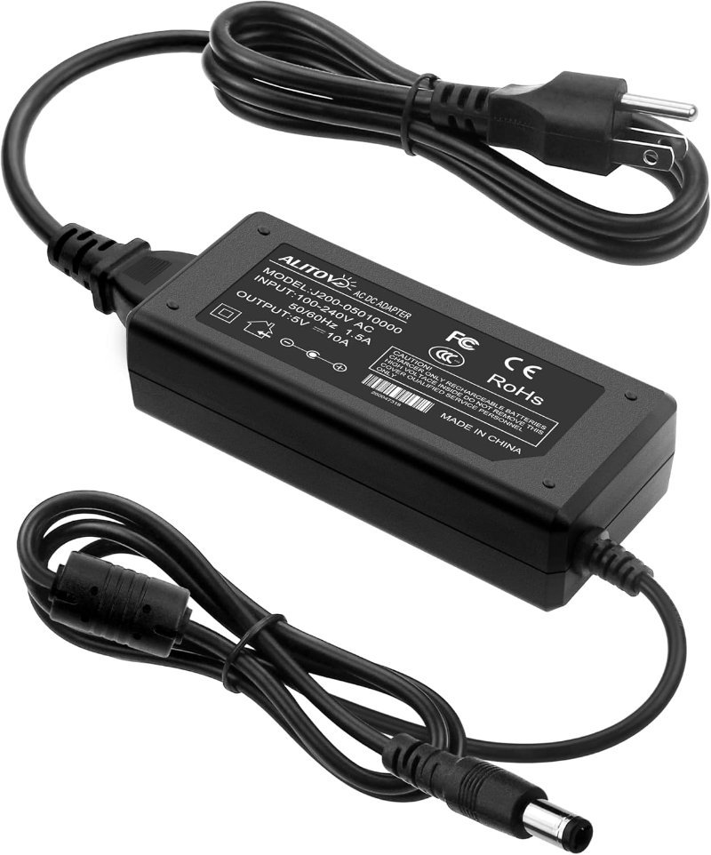
50W of headroom on a 5.5×2.5 mm barrel jack. Enough current that three MG996R servos starting at the same instant is a non-event instead of a brownout.
Check Price on Amazon →If you’re wondering why the servos want 5–6 V while some of your other boards want 3.3 V, and what happens when you mix them, that’s worth understanding before you wire anything permanent — we covered it in 5V vs. 3.3V Logic Levels, Explained.
Should You Build It?
Yes, with one honest caveat: this is not a two-hour project. The printing alone runs many hours across a dozen-plus parts, and the assembly rewards patience with M3 hardware and a set of hex keys. Print tolerances matter here more than on a typical print — the linkage joints need to move freely without slop, so expect to test-fit, and expect to reprint at least one part after you learn how your printer handles the holes.
What you get in exchange is the rare beginner project that teaches something real. Parallel linkages, torque budgets, current headroom, and the difference between a control signal and a power path are all concepts you will use in every robot you build afterward. Most Arduino projects teach you to copy a wiring diagram. This one teaches you why the diagram looks the way it does.
Print the files, buy metal-gear servos, and give the arm its own power supply. Do those three things and it will work the first weekend.