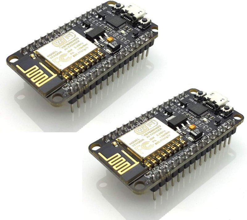
There is a whole category of home automation build that never gets written up properly, because it looks unimpressive in photos. No enclosure, no PCB, no 3D print. Just a thumb-sized board zip-tied inside a light switch box, running firmware someone flashed from a browser tab, quietly reporting to Home Assistant. Multiply that by eleven rooms and you have a house that responds to voice commands, schedules, and motion — with no cloud account, no subscription, and no hub that stops working when a company folds.
The board doing all of that is the ESP8266. It costs about six dollars. This is the single best value in hobby electronics right now and it is not particularly close.
What is actually on the board
The ESP8266 is a Tensilica Xtensa 32-bit LX106 core running at 80 MHz, with a 160 MHz mode you can switch to if you need it. It has roughly 80 KB of usable RAM for your data, and the ESP-12E module that most NodeMCU boards are built around carries 4 MB of flash. Crucially, 2.4 GHz 802.11 b/g/n WiFi is not a shield or an add-on — it is on the die. That is the entire reason this chip took over: networking stopped being a thing you bolt on and started being a thing that was already there.
One warning about the spec lines on Amazon listings for these boards: they are frequently copy-pasted from a decade-old ESP-01 description and will tell you the board has 1 MB of flash. Do not trust it either way. Flash the board, open the Arduino IDE, and check Tools → Flash Size against what the chip actually reports. It matters, because firmware choice depends on it.
The bare chip is not what you buy. You buy a NodeMCU development board, which wraps the ESP-12E module in the two things that make it usable on a desk: an AMS1117 voltage regulator that takes 5 V off USB and hands the chip a clean 3.3 V, and a USB-to-serial bridge (CP2102 or CH340) so your computer can talk to it over a plain USB cable. You get 11 usable digital I/O pins, four of which can do PWM, and exactly one analog input.
Note the 3.3 V. Every GPIO pin on this board is a 3.3 V pin, and putting 5 V on one is a good way to turn a working board into a paperweight. If you have been living in Arduino Uno land where everything is 5 V, this is the adjustment that bites people first — we wrote up why logic levels matter and how to bridge them separately, and it is worth ten minutes before you wire anything to an ESP8266.
The firmware is the actual trick
Here is the part that makes these builds tractable for people who do not want to write a WiFi reconnect loop: you almost certainly should not write the firmware yourself. Two mature open-source projects have already solved it, and both are genuinely good.
Tasmota is a pre-compiled binary. You flash it from a browser using the Tasmota Web Installer — no toolchain, no command line — and then configure the board entirely through a web UI it serves on your local network. Tell it which GPIO pin has a relay on it, which has a sensor, point it at an MQTT broker, done. MQTT, for the uninitiated, is a lightweight publish/subscribe messaging protocol: your board publishes “the light is on” to a topic, and anything subscribed to that topic hears about it. It is the lingua franca of DIY smart homes.
ESPHome takes the opposite approach. You describe the device in a YAML file, and ESPHome compiles that description into custom firmware built for exactly that board. More setup, more power, and it is now formally part of the Home Assistant project, so the integration is seamless — devices appear in Home Assistant without you configuring anything on the Home Assistant side.
My read: start with Tasmota. It gets you to a working, clickable device fastest, and you can reflash the same board to ESPHome later when you want something Tasmota does not do. The one place this recommendation hardens into a rule is the tiny ESP-01 module, where 1 MB of flash makes ESPHome builds uncomfortably tight. On a 4 MB NodeMCU you have room for either, which is another argument for buying the full dev board instead of the bare module.
What it cannot do
One analog input. That is the sharpest limit. If your project needs to read three potentiometers or four analog sensors, you are adding an external ADC or moving to an ESP32. Several GPIO pins (GPIO0, GPIO2, GPIO15) are boot-strapping pins that the chip reads at power-up to decide how to start; hang a relay module on one of those and the board may simply refuse to boot. Check a pinout before you assign pins, not after.
And the honest one: switching household mains voltage is not a beginner project. The people running eleven of these in their walls are, generally, people who know what they are doing with 120 V or comfortable calling an electrician. Switching a 12 V LED strip or a low-voltage DC load is a great weekend build. Switching a wall outlet is a different risk category and deserves to be treated that way.
The board to actually buy
Buy a two-pack. Not because you need two, but because the first one is the one you will misconfigure, brick, or wire backwards while you are learning, and having a known-good spare turns a dead evening into a five-minute swap. HiLetgo’s CP2102 version is the one I keep reaching for — the CP2102 USB-serial chip has better driver support out of the box on modern macOS and Windows than the cheaper CH340 variants, which is one fewer thing to debug on day one.
This post contains affiliate links. If you buy through them, this site earns a commission at no extra cost to you.
Two boards, roughly six dollars each. ESP-12E module, built-in 2.4 GHz WiFi, onboard 3.3 V regulator, and a CP2102 bridge that your computer will recognize without a driver hunt. Runs Tasmota or ESPHome comfortably.
Check Price on Amazon →Relay 1, then click the toggle and listen for the click. Switch something harmless first — a 12 V LED strip, not a wall outlet. If the relay refuses to trigger, that is the classic 3.3 V-driving-a-5 V-input problem, and flipping the module to low-level trigger usually fixes it.
Where this goes
The reason this pattern scales into a whole house is that each node is disposable. A six-dollar board that controls one thing and reports its state over MQTT is a component, not a project. When one dies you swap it. When you want a new sensor you flash another one. There is no central expensive box whose failure takes the system down, and nothing stops working because a manufacturer sunset a cloud API.
Start with one board, one relay, and one lamp you do not care about. Get the toggle in a browser tab to make a physical click across the room. Everything after that is repetition.