Here is the thing nobody tells you when you start wiring buttons: a digital pin does not have two states. It has three. HIGH, LOW, and nobody has told me anything. That third state is where beginner projects go to die, and a pull-up resistor is the two-cent part that eliminates it.
The concept takes about ninety seconds to understand and then quietly explains a dozen unrelated bugs you have already hit. Let’s do the ninety seconds.
The problem: a pin connected to nothing reads as nothing in particular
Wire a pushbutton the obvious way — one leg to pin 2, the other leg to 5V — and you have built a circuit that works half the time. Press the button and pin 2 is connected to 5V, so digitalRead(2) returns HIGH. Fine. Release it, and pin 2 is connected to… nothing. An open wire. SparkFun’s tutorial calls this floating, and floating is not a polite way of saying zero. An input pin is a high-impedance thing that reports whatever voltage it happens to find, and an unconnected wire picks up voltage from stray capacitance, nearby traces, your hand, the mains hum in the room. The reading flickers. Your code sees phantom button presses that you did not make.
A pull-up resistor fixes this by making sure the pin is always connected to something, even when the button is open. You run a resistor from the pin up to 5V (or 3.3V, depending on your board — if that distinction is fuzzy, read 5V vs. 3.3V logic levels first). Now the pin has a weak, permanent path to the supply rail, so with nothing else going on it sits reliably HIGH.
Why the resistor doesn’t just short out when you press the button
This is the part that trips people up, so here it is plainly. With a pull-up, you wire the button between the pin and ground, not between the pin and 5V. The logic inverts: pin reads HIGH when the button is open, LOW when it’s pressed.
Press the button and the pin now has two paths — a 10 kΩ path up to 5V and a near-zero-ohm path down to ground. Ground wins overwhelmingly, so the pin reads LOW. The resistor is still conducting, but it is conducting a trickle: 5V across 10 kΩ is 0.5 mA, which is nothing. That is the whole trick. The resistor is strong enough to define the pin’s voltage when nothing else is connected, and weak enough to lose instantly to anything that is. Which is why you’ll hear them called weak pull-ups — and why wiring the button to 5V without a pull-down on the other side is the version that doesn’t work.
Your Arduino already has pull-ups inside the chip
Here is the good news that saves you a resistor on most projects. Every I/O pin on the AVR chip has a pull-up resistor built into the silicon, switchable per pin. You turn it on with a third argument to pinMode() that a surprising number of tutorials never mention:
void setup() {
  Serial.begin(9600);
  pinMode(2, INPUT_PULLUP);   // button wired from pin 2 to GND
}

void loop() {
  // LOW means pressed - the pull-up holds the pin HIGH otherwise
  if (digitalRead(2) == LOW) {
    Serial.println("pressed");
  }
  delay(50);
}
That is it. INPUT_PULLUP instead of INPUT, button to ground, and the floating problem is gone with zero added parts. Microchip’s datasheet for the ATmega328PB — the immediate sibling of the ATmega328P on an Uno — specs that internal pull-up (symbol RPU) at a minimum of 20 kΩ and a maximum of 50 kΩ. Note the width of that window: the chip does not promise you a value, only a range. For a button, who cares. For anything where the exact resistance matters, that vagueness is exactly why you reach for an external resistor instead.
Worth knowing: INPUT_PULLUP is a per-pin setting on a digital pin, so it interacts with how you’ve configured that pin generally — see digital vs. analog pins if you’re not sure which pins this applies to.
Picking a value, when you do need an external one
The rule of thumb is 10 kΩ, and the rule of thumb is correct for essentially every button, switch, and sensor-enable pin you will ever wire. SparkFun puts the usable window at 10 kΩ to 100 kΩ for avoiding most problems, and the tradeoff across that window is straightforward:
- Lower resistance = a strong pull-up. More current flows, the pin snaps to HIGH faster and shrugs off electrical noise better, and you burn more power whenever the button is held down. A 5 kΩ pull-up on 5V draws about 1 mA when pressed.
- Higher resistance = a weak pull-up. Less wasted current, but the pin takes longer to climb back to HIGH and is easier to upset. Go far enough — SparkFun’s example uses 4 MΩ — and the pull-up stops doing its job reliably at all.
Unless you have a specific reason, use 10 kΩ and stop thinking about it.
Pull-downs are the same idea, upside down
A pull-down resistor runs from the pin to ground instead of to the supply, holding the pin at a defined LOW when nothing is driving it. Wire your button between the pin and 5V with a 10 kΩ pull-down to ground, and you get the non-inverted logic a lot of people find more intuitive: HIGH means pressed.
The catch is that AVR chips give you internal pull-ups only — there is no INPUT_PULLDOWN on an Uno. Every pull-down costs you an actual physical resistor. That asymmetry is the real reason the Arduino world does buttons-to-ground with inverted logic: it’s not a style choice, it’s what the hardware hands you for free.
The one place you cannot cheat: I2C
I2C is the two-wire bus that most sensor breakout boards talk over. Its two lines, SDA and SCL, are not driven HIGH by anybody. Every device on the bus can only pull them down; letting go is how a device signals a one. That means pull-up resistors are not an optional nicety on I2C — they are the only thing that ever makes those lines go HIGH. No pull-ups, no bus.
Here the value genuinely matters, and it’s bounded from both directions. Microchip’s technical brief works the minimum from the spec’s required sink current: a device has to be able to drag the line down to its low-output voltage while sinking at least 3 mA, which for Standard mode (up to 100 kbit/s) and Fast mode (up to 400 kbit/s) puts the floor at 866 Ω on a 3.0V bus and 1.53 kΩ on a 5.0V bus. Go below that and devices can no longer pull the line convincingly low. The ceiling comes from the other end: too much resistance and the line rises too slowly through the bus’s own parasitic capacitance to be read in time, which Microchip expresses as Rp(max) = trise / (0.8473 × Cbus) — longer wires and more devices mean more capacitance, which means a smaller maximum resistor.
The famous 4.7 kΩ figure is not actually in the specification. It’s just a value that sits comfortably inside those bounds for a typical short hobby bus, which is why nearly every breakout board ships with pull-ups already soldered on. And that convenience is a trap, because resistors in parallel add up to less resistance: two 4.7 kΩ breakouts on one bus give you 2.35 kΩ, three give you about 1.57 kΩ, which on a 5V bus is right at the spec’s floor. Stack four sensors and you are below it. If a device that worked alone vanishes once you add another, that’s the first thing to check — the I2C scanner troubleshooting guide walks the rest of it.
What to actually buy
This post contains affiliate links. If you buy through them, this site earns a commission at no extra cost to you.
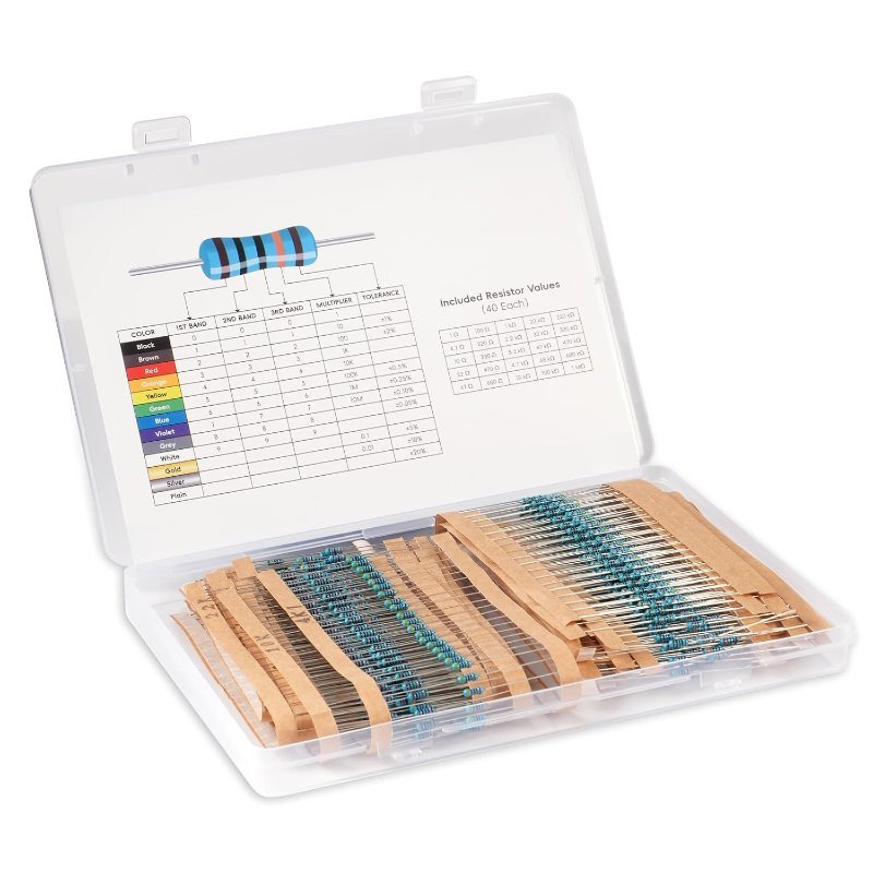
Resistors are the one component you should buy in absurd quantity before you need them, because the alternative is a stalled project waiting four days on a twelve-cent part. A graduated assortment is the right purchase, not individual values. The kit below carries 25 values from 1 Ω to 1 MΩ at 40 pieces each, and critically for this topic it includes both 10 kΩ (your default pull-up) and 4.7 kΩ (your I2C value) rather than skipping awkwardly from 1K to 10K the way some cheaper sets do. The ±1% metal film tolerance is irrelevant for pull-up duty but useful later when you build a voltage divider and want the math to hold.
25 values from 1 Ω to 1 MΩ, 40 of each, ±1% metal film, in a labeled case with the value chart printed on it. Includes 10 kΩ and 4.7 kΩ, which covers every pull-up you will wire for years.
Check Price on Amazon →The other half of learning this is having something to pull up. Tactile pushbuttons are the canonical test case, and the 6×6 mm four-pin kind seats firmly in a breadboard instead of wobbling out of it mid-test. One warning that costs people an afternoon: those four pins are two pairs, each pair permanently shorted together internally. Bridge the wrong two and your button appears to be stuck pressed forever. Wire across the switch, not along it — breadboard wiring basics covers the row-and-column logic that makes this easy to get right.
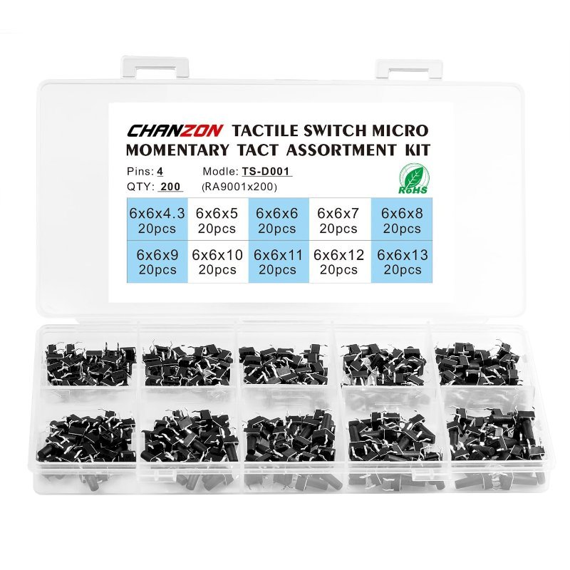
Four-pin momentary tactile switches in a range of plunger heights. Breadboard-friendly, cheap enough to not care when you lose one in the carpet, and the standard part every button tutorial assumes you have.
Check Price on Amazon →pinMode(2, INPUT) with no pull-up, and print digitalRead(2) every 50 ms. Wave your hand near the jumper wire and watch the Serial Monitor flicker between 0 and 1 while you touch nothing. Then change one word to INPUT_PULLUP, move that leg from 5V to GND, and watch the readings go rock solid. For the I2C half of the lesson, put two BMP280 breakout modules on the same bus and run an address scanner — each board brings its own pull-ups along, so you can watch the parallel resistance drop as you add the second one.
When you don’t need one at all
Pull-ups answer exactly one question: what is this pin’s voltage when nothing is driving it? If something is always driving the pin, the question never comes up and the resistor is pointless. An output pin never needs one. A pin wired to another chip’s push-pull output — most sensors’ digital outputs, a shift register, a logic-level converter — never needs one, because that output actively drives both HIGH and LOW. An analog pin reading a potentiometer never needs one, because the pot’s wiper is always connected to something through the pot itself.
Mechanical switches, open-collector outputs, and I2C are the cases that need them, and the first two are covered for free by INPUT_PULLUP. Learn the one word, keep a drawer of 10 kΩ and 4.7 kΩ, and you have retired an entire category of intermittent bug.