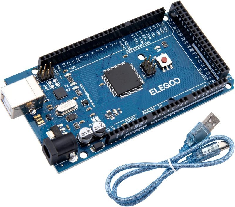
Search for “Arduino arcade cabinet” and most of what you find is, strictly speaking, a Raspberry Pi arcade cabinet with an Arduino bolted onto it. That’s not a knock on those builds. It’s the correct architecture, and the moment you understand why, the whole project stops feeling like a pile of unrelated parts. The Pi runs the emulator. The Arduino runs everything the emulator should never have to think about. And for that second job, a Mega is the right board by a wide margin.
What the Mega is actually doing in there
Here’s the division of labor in a well-built cabinet. The Pi boots RetroPie, pushes frames to the screen, and reads the controls as an ordinary USB gamepad. The Mega handles the cabinet itself: twenty illuminated button LEDs, an RGB marquee across the top, a coin acceptor that has to debounce a mechanical switch reliably, a cooling fan that kicks on above a temperature threshold, and — in the nicest builds — a proximity sensor that wakes the lighting up when someone walks past.
That last one isn’t hypothetical. Bob Clagett’s full-size cabinet build, covered by Make:, uses exactly that trick: a light-up marquee with an Arduino driving the RGB lighting off a proximity sensor, so the machine lights up as you approach it. It’s a small touch that does more for the “this is a real arcade machine” feeling than another 200 ROMs would.
Notice that not one item on that list has anything to do with emulation. They’re all jobs that want steady, predictable, hard real-time behavior and a lot of pins — which is precisely what a microcontroller is good at and what a Linux box running a game emulator is bad at.
The pin math is the whole argument for a Mega
An Uno gives you 14 digital I/O pins and 6 analog inputs. A two-player cabinet with individually controlled button lights eats that budget before you’ve wired the marquee, let alone the coin door and the fan. You can get clever with shift registers and LED driver chips, and plenty of people do — but on a project where you’re already cutting MDF and routing t-molding, “just use a board with enough pins” is a reasonable place to spend twenty dollars instead of a weekend.
The Mega 2560 gives you 54 digital I/O pins, 15 of which do PWM, plus 16 analog inputs, 4 hardware UARTs, and an ATmega2560 running at 5V and 16 MHz with 256 KB of flash, 8 KB of SRAM, and 4 KB of EEPROM. Two of those numbers matter more than the rest here.
PWM — pulse width modulation — is how a digital pin fakes an analog output. The pin can only be fully on (5V) or fully off (0V), so it flips between the two thousands of times per second, and the ratio of on-time to off-time reads as brightness to your eye or as speed to a motor. Fifteen PWM pins means fifteen things you can fade, dim, and pulse independently instead of just switching on and off. That’s the difference between button lights that blink and button lights that breathe.
Four hardware UARTs means four independent serial connections built into the silicon. You can hold a conversation with the Pi on Serial1 while leaving Serial — the one wired to the USB port — free for uploads and debugging. The first time something misbehaves at 1am and you want to watch the Mega’s internal state scroll past in the Serial Monitor without unplugging the cabinet’s brain, you’ll be glad you didn’t have to share a port.
This post contains affiliate links. If you buy through them, this site earns a commission at no extra cost to you.
An ATmega2560 clone with the full 54 digital I/O, 15 PWM, 16 analog, and 4 UARTs, for well under the price of an official board. Importantly for this build, it uses a real ATmega16U2 for its USB interface rather than a cheap CH340 serial chip — which keeps the HID door open if you ever want to walk through it.
Check Price on Amazon →FastLED.addLeds<WS2812B, 6, GRB>(leds, 60) in setup(), and write a slow color sweep. Ten minutes of work, and suddenly the project feels real.
The part that trips almost everyone up: a Mega can’t pretend to be a keyboard
RetroPie reads your controls as a USB keyboard or a USB gamepad. So the obvious plan is to wire the joysticks and buttons to the Mega’s digital pins and have it send keystrokes over USB. That plan does not work out of the box, and finding out why after you’ve already wired 20 buttons is a bad afternoon.
The ATmega2560 has no USB hardware in it at all. The board’s USB-B port is wired to a completely separate chip — an ATmega16U2 — whose only factory job is translating USB into serial so your computer can talk to the main processor. The Keyboard.h and Mouse.h libraries you’ve seen in Leonardo and Pro Micro tutorials work because those boards use an ATmega32U4, which has native USB built into the same chip that runs your sketch. Put Keyboard.begin() in a Mega sketch and it won’t even compile.
There is a real way around it. NicoHood’s HoodLoader2 replaces the 16U2’s factory DFU bootloader with one you can flash from the Arduino IDE, which turns that second chip into a fully programmable USB device — HID keyboard, mouse, gamepad, CDC serial, plus seven I/O pins of its own — while the ATmega2560 stays reprogrammable as normal. It works, it’s well documented, and people have shipped arcade builds on it. It also means flashing a bootloader over ICSP with a second Arduino as a programmer before you’ve played a single game of Galaga.
If that sounds like a project you want, it’s a great one. If it sounds like a detour, there’s a twenty-five dollar answer.
Just buy the encoder
A zero-delay USB encoder is a small board that does one thing: enumerate as a USB gamepad and read up to a dozen or so switch closures. The harnesses are pre-made, with 5-pin connectors that push straight onto the spade terminals of the microswitches inside your joystick and buttons. No soldering, no bootloader, no HID library. You plug it into the Pi and RetroPie sees a controller.
“Zero delay” is marketing — nothing is zero — but the latency these add is far below what you’ll notice playing anything from the era this cabinet exists to celebrate. Buying the joysticks, buttons, and encoders as a matched kit also saves you the specific misery of discovering that your buttons are 28mm and your panel holes are 30mm.
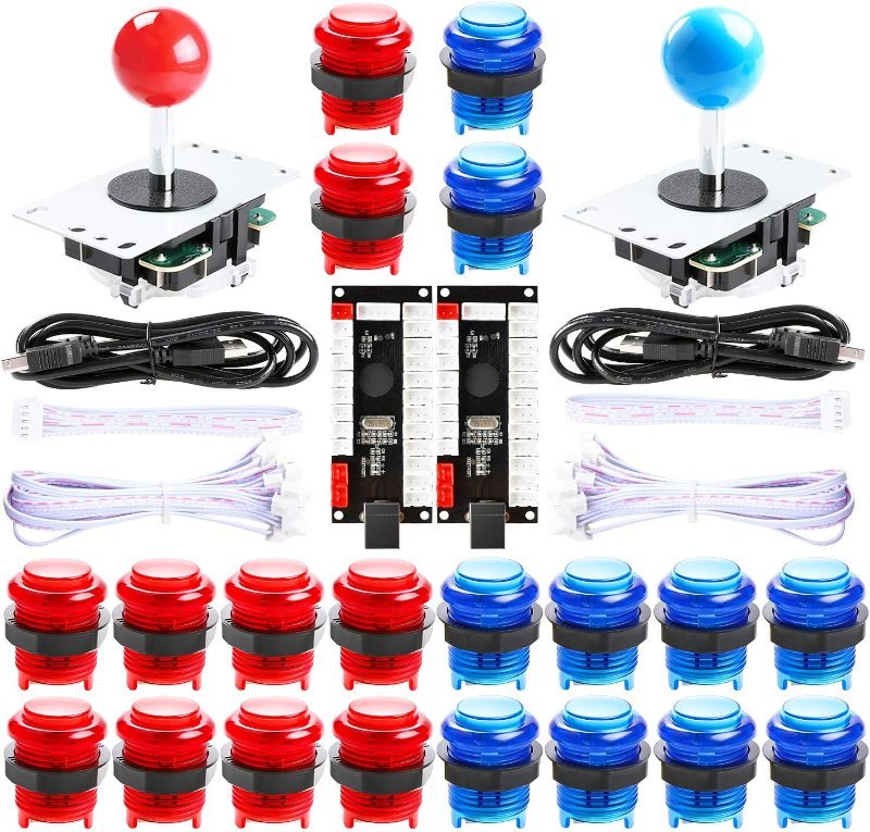
Two joysticks, 20 LED-illuminated buttons, and two zero-delay USB encoders with the wiring harnesses already made up. This is the fastest path from a cut control panel to a cabinet that plays games — and the lit buttons are what give the Mega something to actually control.
Check Price on Amazon →Wiring the Pi and the Mega together without releasing smoke
If you want the Pi to tell the Mega what’s happening — flash the marquee on a coin insert, recolor the buttons when you switch from NES to Neo Geo — the two need a channel between them. The tempting one is a direct serial link from the Pi’s GPIO header to the Mega’s Serial1 pins. Do that carelessly and you will kill the Pi.
The Pi’s GPIO pins run at 3.3V. The Mega’s run at 5V. Pi-to-Mega is usually fine, because the Mega reads anything above roughly 3.0V as HIGH. The Mega-to-Pi direction is the dangerous one: it puts 5V into a pin rated for 3.3V, and the Pi has no protection on those pins. Use a level shifter, or at minimum a resistor divider on that single line. We wrote up the whole issue in 5V vs. 3.3V logic levels, and this is exactly the situation it exists for.
The lazier and safer option: run a USB cable from the Pi to the Mega’s USB-B port and talk over that. It’s a serial link either way, the voltage problem disappears entirely because the USB chip handles it, and you get a convenient way to reflash the Mega without opening the cabinet.
Why this makes such a good first big build
Most beginner electronics projects live on a breadboard and die there. A cabinet doesn’t let you do that. You have to distribute power to a screen, a Pi, a Mega, an LED strip, and twenty button lights without brownouts. You have to make two computers agree on a protocol. You have to put it in a box that a human being interacts with by hitting it. Every one of those is a skill that transfers to whatever you build next, and none of them are things you learn from blinking an LED.
Start with the control panel and the encoder, because that’s the part that turns a monitor into a game. Add the Mega and the lighting second, once you’re already playing. And if you’re still working out which board should be doing what in a build like this, our breakdown of Arduino versus Raspberry Pi covers the same division of labor in the general case.