A commercial video doorbell runs about $100 up front and then politely asks for a few dollars a month before it will let you watch footage recorded by a camera you already own. The version in this guide costs roughly $35 in parts, keeps every photo inside your own house, and sends a picture of whoever is standing on your porch straight to your phone. It is also fussier, slower, and uglier than the store-bought one. That trade is the whole point.
This is a full build walkthrough, not a highlight reel. I am going to spend more time on the two things that actually sink this project for beginners — the pin conflicts and the power supply — than on the fun parts, because the fun parts mostly work on the first try and those two do not.
What we are actually building
Press a physical button mounted outside your door. The board wakes up, takes a still photo, and pushes it to a Telegram chat on your phone within a few seconds. No subscription, no cloud recording service, no company holding your porch footage. Telegram is doing the heavy lifting here as a free message transport — you are not building an app, you are borrowing one that already has push notifications solved.
Deliberately out of scope: continuous video streaming, two-way audio, and battery operation. All three are possible on this hardware and all three turn a weekend project into a month-long one. Get the still-photo version working first.
Why this needs an ESP32-CAM and not an Arduino Uno
If your instinct was to reach for an Uno, the numbers explain why that does not go anywhere. The ATmega328P on an Uno has 2 KB of SRAM and 32 KB of flash. A single 640×480 JPEG off a cheap camera module lands somewhere around 30–50 KB — the photo alone is larger than the Uno’s entire program storage, never mind its working memory. The Uno also has no Wi-Fi radio and no camera interface, so it could neither capture the image nor send it.
The ESP32-CAM solves all of that on one board: a dual-core 240 MHz ESP32-S chip, 520 KB of internal SRAM plus 4 MB of external PSRAM (the extra memory is what actually holds the frame buffer), integrated 2.4 GHz Wi-Fi, a dedicated parallel camera interface, and an OV2640 2-megapixel sensor on a ribbon cable. PSRAM matters more than it sounds: without it the camera driver simply cannot allocate a buffer large enough for anything above thumbnail resolution.
This post contains affiliate links. If you buy through them, this site earns a commission at no extra cost to you.
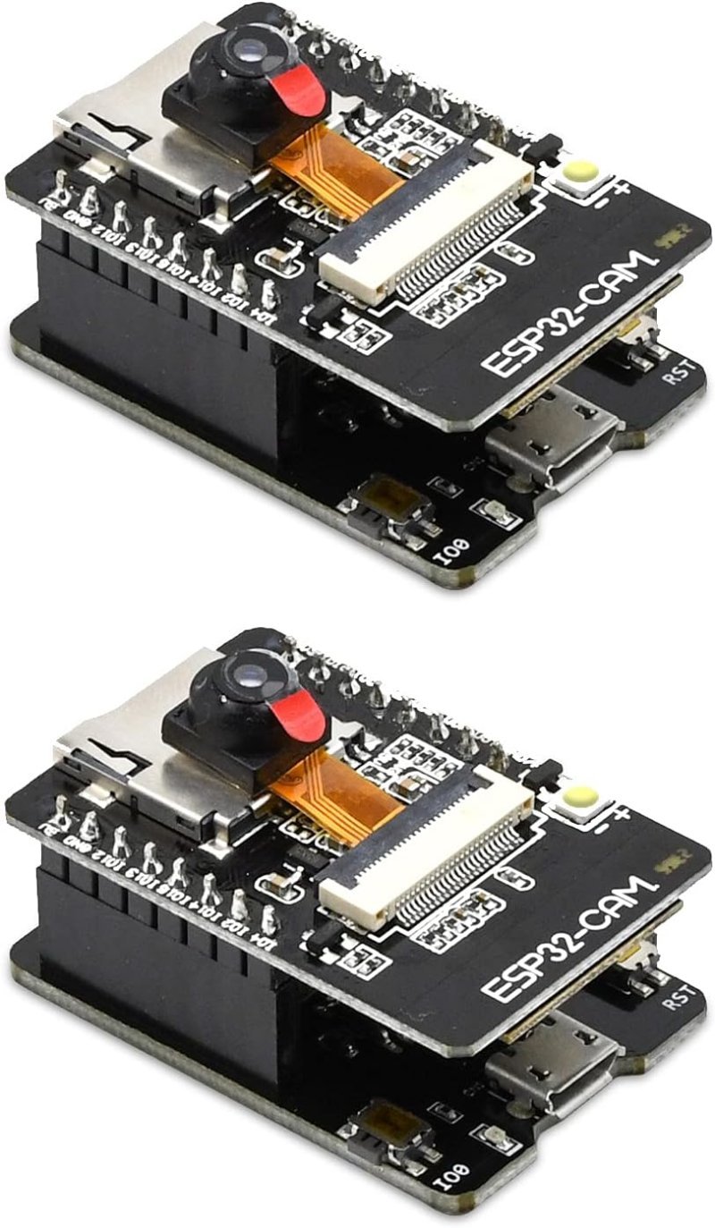
Buy the version that ships with the ESP32-CAM-MB baseboard. The bare ESP32-CAM has no USB port at all — programming it means wiring an external USB-to-serial adapter and manually jumpering GPIO 0 to ground every single time you want to flash new code. The MB baseboard is a carrier with a CH340G USB chip and a boot button that handles that dance for you. It costs about two dollars more and saves you an hour of frustration on day one.
Two complete ESP32-CAM boards with OV2640 cameras and two MB programmer baseboards. Buy the two-pack — you will brick one learning the flashing procedure, and having a known-good spare to compare against is worth more than the price difference.
Check Price on Amazon →The pin situation, which is the part nobody warns you about
The ESP32 chip has plenty of GPIO. The ESP32-CAM board does not, because the camera has already claimed most of it. The OV2640 interface occupies GPIO 0, 5, 18, 19, 21, 22, 23, 25, 26, 27, 32, 34, 35, 36, and 39. The microSD slot, if you use it in its default 4-bit mode, takes GPIO 2, 4, 12, 13, 14, and 15 on top of that — and GPIO 4 doubles as the blinding white flash LED, which is why that LED sometimes flickers when you write to the card.
What is left for you: GPIO 13 and GPIO 16, comfortably. GPIO 12 works but comes with an asterisk — it is a strapping pin (MTDI) that the chip samples at boot to decide the internal flash voltage. If GPIO 12 is held HIGH while the board powers up, the ESP32 can refuse to start. If you must use it, only drive it after boot and never pull it up.
If you do want the SD card and your own pins, initialize it in 1-bit mode with SD_MMC.begin("/sdcard", true). That second argument tells the driver to use only the D0 line instead of D0–D3, which hands GPIO 12 and GPIO 13 back to you at a modest cost in write speed. For a doorbell that saves one photo every few hours, that speed penalty is irrelevant.
One more thing worth internalizing: the ESP32 is a 3.3 V logic device. Every sensor you attach needs to speak 3.3 V on its signal line, and feeding a 5 V signal into a GPIO pin is how you kill the chip. If that distinction is new to you, read 5V vs. 3.3V Logic Levels, Explained before you wire anything — it is the single most common way beginners destroy a board.
The button, and why “momentary” is not optional
A doorbell button must be momentary: closed only while your finger is on it, open the instant you let go. The visually identical latching button clicks and stays clicked until pressed again. Buy a latching switch by mistake and your doorbell will fire once, then sit there permanently “pressed” until someone goes outside and pushes it a second time. Product listings bury this distinction in the fine print, so read it carefully.
Wire one leg of the button to GPIO 13 and the other leg to GND, then declare the pin with pinMode(13, INPUT_PULLUP). The chip’s internal pull-up resistor holds the pin HIGH on its own; pressing the button shorts it to ground and it reads LOW. This is why you do not need an external resistor, and it is also why the logic reads backwards from what you would expect — pressed means LOW.
Add debouncing. A mechanical switch does not close cleanly; the contacts bounce for a few milliseconds and the ESP32 is fast enough to register that as five or six separate presses. Ignore any state change that happens within about 50 ms of the last one and the problem disappears. Skip this step and your first visitor will send you six identical photos.
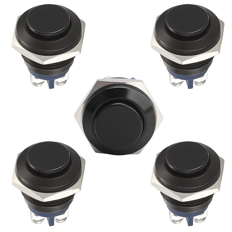
Momentary, normally open, no LED to complicate the wiring, and an IP65-rated aluminum shell that survives being mounted outdoors. The 5/8-inch mounting hole fits a standard doorbell plate. Five in a pack means you can prototype indoors and still have spares.
Check Price on Amazon →Power is where this project actually dies
More ESP32-CAM builds fail here than everywhere else combined, and the failure looks like a software bug, which is what makes it so maddening. Your board boots, connects to Wi-Fi, then reboots the moment it tries to take a photo. The serial monitor prints Brownout detector was triggered and the cycle repeats forever.
The cause is current. With the Wi-Fi radio transmitting and the camera active at the same time, the board can pull around 310 mA in bursts. The ESP32’s brownout detector resets the chip whenever the supply rail sags below roughly 2.45 V. A thin USB cable, a laptop port that throttles current, or a marginal wall wart will all let the rail dip that far during a transmit burst — and the reset lands right at the moment the code does something demanding, which is exactly why it reads like a code problem.
Three fixes, all cheap. Power the board through its 5V pin from a supply rated for at least 2 A. Do not use the pin labeled VCC — on the AI-Thinker board that is a power output, not an input, and connecting a supply to it is a well-documented way to let the smoke out. And solder a 470 µF electrolytic capacitor across 5V and GND close to the board; it acts as a local reservoir that covers the millisecond-scale current spikes your wall adapter is too slow to respond to.
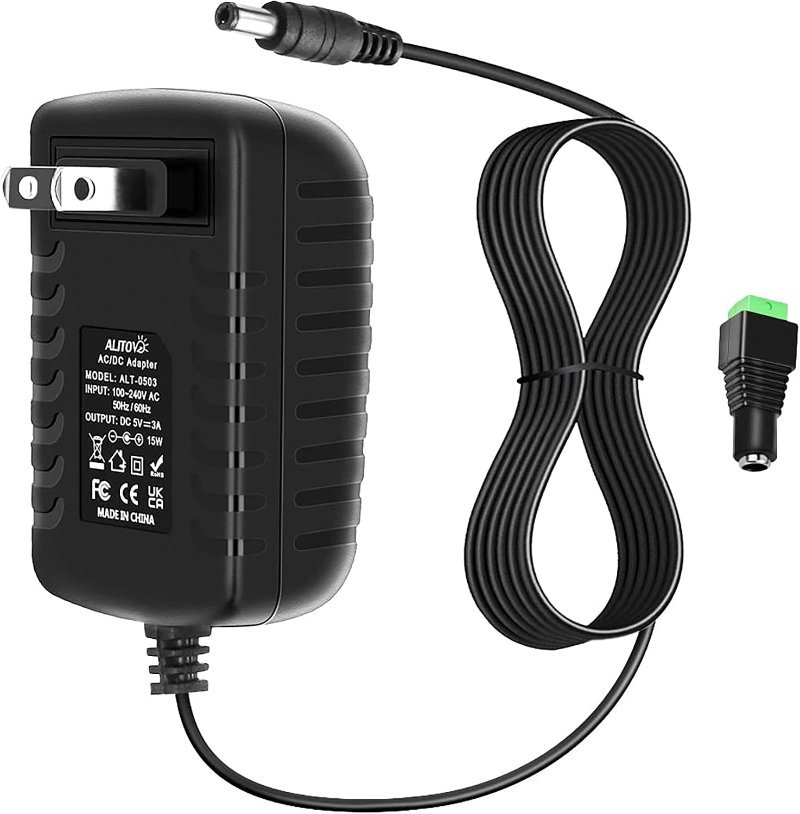
Three amps at a clean 5 volts, with a standard 5.5×2.1 mm barrel plug you can cut off and screw into a terminal block. Overkill for one ESP32-CAM by design — the headroom is what keeps the rail from sagging when the Wi-Fi radio and camera fire at once.
Check Price on Amazon →The firmware, in plain terms
In the Arduino IDE, add the ESP32 boards package by pasting https://espressif.github.io/arduino-esp32/package_esp32_index.json into File → Preferences → Additional Board Manager URLs, then installing “esp32” from the Boards Manager. Select AI Thinker ESP32-CAM as the board. Then change the Partition Scheme to Huge APP (3MB No OTA/1MB SPIFFS) — the camera driver plus a TLS stack plus a JSON parser will not fit in the default partition, and the error you get if you forget is an unhelpful “sketch too big.”
Two libraries do the messaging: UniversalTelegramBot and ArduinoJson, both installable from the Library Manager. Create your bot by messaging @BotFather on Telegram with /newbot; it hands back an API token. You also need your own numeric chat ID, which @userinfobot will tell you if you message it. Hardcode both into the sketch alongside your Wi-Fi credentials.
The main loop is genuinely short: poll GPIO 13, and on a debounced press call esp_camera_fb_get() to grab a frame buffer, hand that buffer to the Telegram library’s photo-send call, then release it with esp_camera_fb_return(). That last line matters — forget it and you leak the frame buffer, and the board runs out of PSRAM and crashes after four or five photos.
If the upload itself refuses to start, that is a separate and very common problem with its own fixes — see Arduino IDE Won’t Upload: The Most Common Causes and Fixes.
Wiring it up, step by step
- Seat the ESP32-CAM into the ESP32-CAM-MB baseboard, camera ribbon facing away from the USB port. Connect USB and confirm the board enumerates as a serial port before you wire anything else.
- Flash a stock CameraWebServer example first, purely to prove the camera and Wi-Fi work. Debugging a doorbell sketch on hardware you have not validated is a waste of an evening.
- Cut the barrel plug off the 5 V supply, identify polarity with a multimeter, and land the positive lead on the board’s 5V pin and the negative on GND.
- Solder the 470 µF capacitor across those same two pins — striped side to GND. Electrolytics are polarized and installing one backwards makes it vent.
- Run two wires out to the button: GPIO 13 to one terminal, GND to the other. Polarity does not matter on a simple switch.
- Upload the doorbell sketch, open the Serial Monitor at 115200 baud, and press the button. You should see the capture logged and a photo land in Telegram within a few seconds.
- Only once all of that works, move it into an enclosure. Mount the camera behind a hole rather than glass — any glazing in front of the lens will reflect the flash LED straight back into the sensor.
What it does well, and what it does not
Expect three to six seconds between the press and the notification arriving. Most of that is Wi-Fi reconnection and the TLS handshake with Telegram’s servers, not the camera. Keeping the board connected instead of sleeping between presses cuts it roughly in half at the cost of constant power draw — fine, since this thing is wall-powered anyway.
The OV2640 is a 2-megapixel sensor with a small lens and no infrared cut filter management to speak of. Daytime photos are perfectly recognizable. Night photos are poor unless you trigger the onboard flash LED on GPIO 4, which will also blind whoever is standing there. A porch light on a timer is a better answer than fighting the sensor.
This is not a Ring replacement and pretending otherwise sets you up to be disappointed. What it is: a real, working device you built and fully understand, with no monthly fee and no third party holding footage of your front door. If you want to take the same components further, the wiring and notification pattern here is most of what you need for an Arduino-based alarm system — swap the button for a reed switch on a door frame and the logic barely changes.