A line-following robot is the first build where your code has to argue with physics. Blink an LED and the LED obeys. Tell a robot to follow a curve and it overshoots, oscillates, clips the corner, and skates off into the carpet — because by the time your sensors notice the line has moved, the chassis is already somewhere else. That gap between sensing and reacting is the entire lesson, and it costs about $40 to learn.
This is the step-by-step build. If you would rather see the finished thing first, we covered a beginner-friendly line follower build from the highlight angle. This post is the parts, the wiring, and the code.
What the robot is actually doing
Strip away the robotics vocabulary and a line follower runs one loop, forever: look down, decide how far off-center you are, and adjust the two wheel speeds to correct. That is it. There is no map, no memory, no path planning. The robot has no idea where it is going and does not need to — it only needs to know whether the black line is currently to its left, its right, or underneath it.
That loop needs to run fast. An Arduino Uno’s 16 MHz processor is far more capable than this job requires; a 100 Hz control loop — a hundred look-and-correct cycles per second — leaves the chip mostly idle. The bottleneck is never the math. It is the mechanical delay between your motors changing speed and the robot actually turning.
The parts list
Five things, and one of them you probably already own:
- A 2WD chassis with two TT gear motors — the yellow plastic gearboxes, usually 48:1, with a caster wheel at the back. We compared the good ones in our robot chassis kit roundup, so pick one there rather than re-litigating it here.
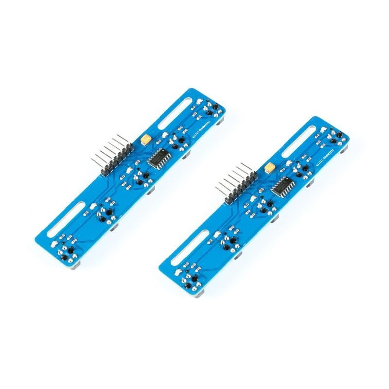
- A 5-channel infrared line sensor array — the part that does the actual seeing.
- An L298N dual H-bridge motor driver — the part that lets a 5 V logic pin control a motor that draws far more current than the pin can supply.
- An Arduino Uno — a Nano works fine too and weighs less, which matters more on a robot than it does on a desk.
- A separate battery pack for the motors — 4×AA (6 V) or a 7.4 V LiPo. Not the Arduino’s 5 V pin. Never the Arduino’s 5 V pin.
This post contains affiliate links. If you buy through them, this site earns a commission at no extra cost to you.
The sensor array is the whole project
Each channel on the array is a TCRT5000: an infrared LED pointed at the floor and an infrared phototransistor sitting right next to it, measuring how much of that light bounces back. White floor reflects a lot. Black electrical tape reflects almost none. The module compares that reflected level against a threshold you set with a tiny onboard trimpot and hands the Arduino a clean digital HIGH or LOW.
Height matters more than beginners expect. The TCRT5000’s usable reflective range is roughly 1 to 8 mm, peaking somewhere around 2.5 mm. Mount the array an inch off the ground and every channel will read the same mush regardless of what is under it. Mount it too low and it scrapes. Aim for a few millimeters and make the mount adjustable, because you will adjust it.
Five channels is the sweet spot for a first build. With one sensor you know only whether you are on the line. With five you know roughly how far off you are — assigning weights of -2, -1, 0, +1, +2 to the channels and averaging the ones that see black gives you a position number instead of a yes/no, and a position number is what makes smooth steering possible.
Five TCRT5000 channels on one board, each with its own threshold trimpot, running on anything from 3.3 V to 5 V. Digital output only, which is the right trade for a first build — you get five clean signals instead of five noisy analog readings to filter. The 2-pack matters: you will eventually crack a board or want a second robot.
Check Price on Amazon →One caveat worth knowing before you buy: this board outputs digital only. If you later want true PID control — where the correction is proportional to how far off you are, plus how fast the error is growing — you will want an array with analog outputs so you can compute a continuous position rather than a stepped one. For a first robot that is a problem for future you.
The motor driver, and the volts it quietly eats
You cannot wire a motor to an Arduino pin. A digital pin sources tens of milliamps; a TT motor under load pulls hundreds. The H-bridge exists to bridge that gap — your pin controls the driver, the driver switches the battery. We went deep on the mechanism in how motor drivers actually work.
The L298N is the standard beginner choice, and it has one specific quirk that eats a lot of first builds. It switches with bipolar transistors, which drop roughly 1.4 V to 2 V as heat. Feed it 6 V from four AA cells and your motors see somewhere around 4 V to 4.6 V. If your robot is sluggish or one wheel refuses to start from a standstill, that voltage tax is usually why — move to a 7.4 V pack before you start suspecting your code.
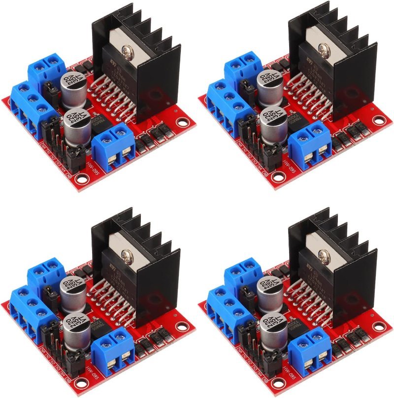
The workhorse. Screw terminals for the motors and battery, a heatsink that actually matters once you are pushing both channels, and an onboard 5 V regulator you can use to power the Arduino from the same pack. Comes with the standoffs, which sounds trivial until you are trying to mount it to acrylic.
Check Price on Amazon →Two wiring rules that are not optional. First, the Arduino ground, the L298N ground, and the battery negative all connect together — without a shared ground reference the driver cannot read your logic signals at all, and the symptom looks like random behavior rather than a wiring fault. Second, if you are mixing a 3.3 V board into this later, read up on 5 V vs. 3.3 V logic levels first.
Wiring it up
The five sensor outputs go to five digital pins — 2 through 6 is convenient. They are pure on/off signals, so digital inputs are exactly right; if the difference between a digital and an analog pin is still fuzzy, we explained it here.
The L298N needs six pins from the Arduino: IN1 and IN2 set the direction of the left motor, IN3 and IN4 the right, and ENA and ENB control speed. Those last two must land on PWM-capable pins — on an Uno that means 3, 5, 6, 9, 10, or 11 (they are marked with a tilde on the board). PWM, pulse-width modulation, is how a digital pin fakes an in-between voltage: it switches on and off thousands of times a second, and the fraction of time it spends on determines the average power reaching the motor. analogWrite(ENA, 255) is full speed; analogWrite(ENA, 120) is a bit under half. Put ENA on pin 9 and ENB on pin 10 and the rest of the pins fall into place.
The code: get it stupid first
Resist the urge to write PID on day one. Start with what is unglamorously called bang-bang control: if the line is under the center sensor, drive both motors forward at the same speed. If it drifts left, slow the left motor. If it drifts right, slow the right one. If all five sensors see white, keep turning in the direction you last saw the line until you find it again.
This will work, and it will look terrible. The robot will weave down the line like it is failing a sobriety test, because every correction is full-strength regardless of how far off it actually is. That weaving is the point — it is the physical demonstration of why proportional control exists. Once you have watched it happen, replace the if-else ladder with a weighted position calculation and multiply the correction by how large the error is. The same robot, same hardware, will glide.
Keep your top speed low while tuning. A slow robot has more time to correct, so it forgives a bad control loop. Speed is the last thing you add, not the first.
When it does not work
Three failures account for most of them. If the robot ignores the line entirely, your thresholds are wrong — go back to the Serial Monitor and turn the trimpots until the channels actually flip between tape and floor. If it drives in a lazy arc with no line present, one motor is faster than the other; trim it in software with a small offset rather than trying to fix it mechanically. And if it works on your desk but fails on the kitchen floor, that is glare — glossy surfaces bounce infrared unpredictably. Matte poster board and matte tape are worth the two dollars.
What to build next
Once it tracks a loop reliably, the natural upgrades are all software: add proportional correction, then derivative damping, then handle intersections by counting how many channels see black at once. The hardware you already have will carry all of it. That is the argument for building the simple version first — you are not going to outgrow the robot, only the code running on it.