A motor that does absolutely nothing is the most demoralizing failure in beginner robotics. A blinking LED at least confirms the board is alive. A dead motor gives you nothing — no sound, no twitch, no error in the Serial Monitor. And because there is no feedback, the instinct is to go rewrite the sketch, which is almost never where the problem lives.
Four times out of five, it is power. Work this list in order — it runs from most likely to least likely, and every step is something you can confirm in about a minute.
1. Stop trying to power the motor from the Arduino
The 5V pin on an Uno is fed by the board’s onboard regulator, and it exists to run sensors and logic chips — parts that sip a few milliamps. A small DC gearmotor pulls hundreds of milliamps just spinning free in the air, and several times that in the instant it starts or whenever it stalls against something. Wire one to the 5V pin and you get one of two outcomes: the motor twitches and quits, or the entire board browns out and resets in the middle of your sketch. Neither one means the motor is broken.
Motors get their own supply, wired into the driver’s motor-voltage terminal — the screw terminal labeled VMS or +12V on an L298N board — with the Arduino powered separately over USB or its barrel jack. If you have a motor connected to an Arduino pin with no driver in between at all, that is the whole bug. Fix that first and re-test before reading further.
2. Account for the driver’s voltage drop
This is the step that catches people who did everything else right. The L298N — the blue-and-black board in nearly every beginner robotics kit — builds its H-bridge out of bipolar junction transistors, and those transistors swallow roughly 1.8V to 2.2V at around 1A of draw. Push 2A through it and the drop climbs toward 4V, per the datasheet.
Now do the arithmetic on a 6V gearmotor fed from a 6V pack. The motor sees about 4V on a good day, and less than that under mechanical load. A small motor with any friction in its gearbox will not break away from a standstill on 4V. It hums quietly, or it sits there silently, and either way you conclude the driver is defective when it is behaving exactly as designed.
The working rule: feed the driver about 2.5V above your motor’s rated voltage. A 6V TT gearmotor wants an 8.4V or 9V pack, not a 6V one. If you would rather not pay that tax at all, MOSFET-based drivers like the TB6612FNG or DRV8833 drop a small fraction of a volt instead of two full volts — our piece on how motor drivers actually work covers why the two topologies behave so differently.
3. Check the enable pins
On an L298N, the ENA and ENB pins gate the two output channels. If enable sits LOW, that channel is dead no matter what your direction pins are doing. Boards ship with little plastic jumper caps on ENA and ENB that tie them permanently HIGH — full speed, no speed control — and there are two distinct ways to get this wrong.
- You pulled the jumper off so you could wire ENA to a PWM pin, but your sketch never actually writes to that pin, or writes a value of zero. Enable stays LOW. Nothing spins, and the code looks perfectly reasonable.
- You left the jumper on and ran a wire from an Arduino pin to ENA. That connects an output pin straight to the board’s 5V rail. Best case nothing happens; worst case you damage the pin.
Pick one arrangement and commit: jumper on with no wire, or jumper off with an analogWrite() driving that pin. PWM — pulse width modulation — is how an Arduino fakes an analog output. It flips the pin on and off thousands of times a second, and the fraction of each cycle spent HIGH determines the effective voltage the motor sees. That matters here because analogWrite(enaPin, 0) is a hard off, and anything under roughly 50 out of 255 usually will not produce enough torque to overcome static friction. The motor reads as broken while the wiring is fine.
4. Tie the grounds together
Two power supplies with two separate grounds means the driver has no shared reference for the logic signals your Arduino is sending it. Your board thinks it is putting out a clean HIGH; the driver has no way to agree on what HIGH means. The battery’s negative terminal, the driver’s GND, and the Arduino’s GND all need to be electrically joined. It is one jumper wire, it costs nothing, and it is the single most common omission in a motor circuit that looks correct in a photo.
Related trap: if you are driving a 5V motor driver from a 3.3V board like an ESP32, the driver may not reliably register your logic HIGH even with grounds tied. That is a different failure with the same symptom — see 5V vs. 3.3V logic levels, explained.
5. Confirm the motor itself is alive
Disconnect the motor from everything and touch its two leads directly across a battery pack for a second. If it spins, the motor is fine and your problem is upstream in the driver or the wiring. If it does nothing, you have isolated the fault to the cheapest replaceable part in the build. Brushed motors do genuinely fail — a stalled motor held against a load will cook its own windings surprisingly fast, and kit motors are not built to survive that.
While you are there, tug gently on the solder joints at the motor terminals. Kit motors arrive with thin, brittle wire tacked to fragile tabs, and a lead that has snapped flush against the casing looks completely intact from two feet away.
Stop guessing and start measuring
Every step above is a hypothesis until you put a probe on it. Is the pack actually at 9V, or has it sagged to 6V under load? Is ENA really HIGH? Is there continuity through that motor winding at all? These are not questions you can answer by staring at a breadboard, and they take about ninety seconds to answer with a meter. Buying one is the highest-leverage twenty dollars in this hobby — it converts a whole category of mystery failures into a number you can read off a screen.
This post contains affiliate links. If you buy through them, this site earns a commission at no extra cost to you.
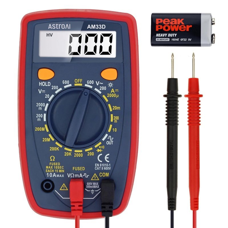
You do not need a nice one. For everything in this checklist you need DC voltage, resistance, and a continuity beeper — features that every meter on the market has had for forty years. The AstroAI 2000-count meter is the one I hand to people starting out: it has the continuity buzzer, the probes are adequate, and losing it in a move costs you nothing. Spend the difference on motors.
DC/AC voltage, current, resistance, continuity and diode test. Everything this checklist asks you to measure, and nothing you will not use.
Check Price on Amazon →The checklist, in order
- Is the motor on its own supply through a driver, not hanging off the Arduino’s 5V pin?
- Is that supply at least 2.5V above the motor’s rating, to cover the L298N’s drop?
- Is enable HIGH — jumper installed, or a PWM value well above zero?
- Are the battery ground, driver ground, and Arduino ground all tied together?
- Does the motor spin when touched straight to a battery, bypassing everything?
- Are the direction pins actually opposite? Both HIGH or both LOW is a brake, not a spin.
That last one deserves a note, because it is the one purely-software cause on the list. An H-bridge spins a motor by pulling one terminal high and the other low. Set IN1 and IN2 to the same state and you have shorted both motor terminals together, which is an active brake — the motor will resist being turned by hand and will not move on its own. If your motor feels stiff rather than free-spinning when it is supposed to be running, check those two pins before you check anything else.
Run the list top to bottom and you will find it. In my experience steps 1, 2, and 4 account for the overwhelming majority of dead motors, and all three of them are power problems wearing a costume.