Three motor types live in every hobbyist’s parts drawer, and most people choose between them by vibe. That’s how you end up with a servo bolted to a drive wheel it can’t turn all the way around, or a stepper motor and a $9 driver board doing a job a $3 gearmotor would have done quieter and cheaper. The choice isn’t actually a matter of taste. There’s one question that settles it almost every time, and once you’ve asked it the right answer is usually obvious.
If you want the deeper explanation of how each type actually works internally, we covered that in Servos vs. DC Motors vs. Stepper Motors. This post is the buying decision — which one to put in the cart, and which specific part is worth your money.
Ask this first: does the shaft need to know where it is?
Every one of these motors turns a shaft. The difference is what the shaft knows about its own position, and whether you can command a position at all.
A plain DC motor knows nothing. You apply voltage, it spins; you cut voltage, it coasts to a stop somewhere. A servo knows exactly where it is, because there’s a potentiometer inside geared to the output shaft and a little control circuit that constantly drives the motor toward whatever angle you commanded — but it can only reach angles inside a roughly 180° arc. A stepper knows where it is only by counting: it moves in fixed increments, and if your code has counted every increment since startup, it knows the position without any sensor at all — forever, in either direction, past as many full revolutions as you like.
So: don’t care about angle → DC. Need a specific angle inside half a turn → servo. Need a counted position with unlimited rotation → stepper. The rest of this post is what that means in practice, and what to buy for each.
DC gear motors: the right answer more often than beginners expect
A gearmotor is a fast, weak DC motor with a gearbox bolted to the front that trades that speed for torque. It’s the cheapest continuous rotation you can buy, and for anything that just needs to go — drive wheels, a fan, a conveyor, a tumbler — it’s the correct choice. You control speed with PWM, which stands for pulse width modulation: the Arduino can’t actually output half a volt of “half speed,” so instead it switches the pin fully on and off thousands of times a second and varies the ratio of on-time to off-time. analogWrite(pin, 128) means “on about half the time,” and the motor, which can’t react that fast mechanically, behaves as though it’s getting about half the voltage.
The catch is that a motor draws far more current than an Arduino pin can supply, so you never wire one to a pin directly — it goes through a driver board, which is a topic worth its own read in How Motor Drivers Actually Work.
This post contains affiliate links. If you buy through them, this site earns a commission at no extra cost to you.
For robot-scale work, the yellow 1:48 TT gearmotor is the default for a reason. This four-pack runs on 3–6V, spins about 200 RPM unloaded at 6V, and stalls at roughly 0.8 kg·cm — enough to push a small chassis around a flat floor and not much more, which is exactly the honest spec range for the job. The dual output shaft matters more than it sounds: the back stub is there so you can slip an encoder disc onto it later if you decide you want closed-loop speed control.
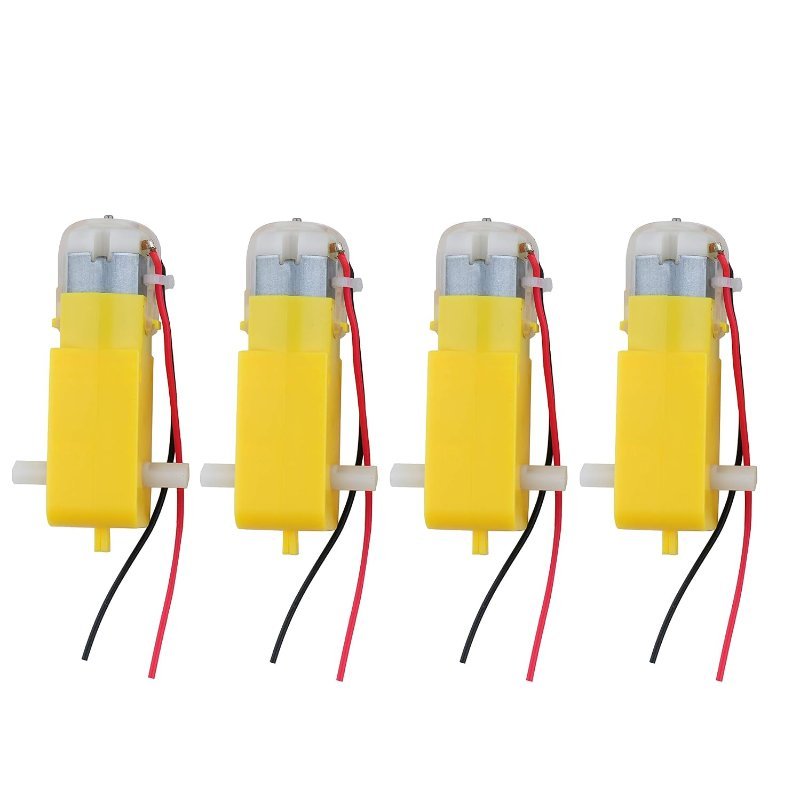
200 RPM at 6V, 0.8 kg·cm stall torque, dual shaft, pre-soldered 2.54mm leads. Four of them is a full drivetrain for under the cost of one servo.
Check Price on Amazon →Servos: when the part must reach a known angle and stay there
A hobby servo is a closed-loop package: DC motor, gearbox, position sensor, and controller in one case, with three wires out. You don’t drive it with PWM in the speed sense — you send it a pulse roughly every 20 milliseconds (50 Hz), and the width of that pulse is the command. About 1000 microseconds means one end of travel, 2000 microseconds means the other, 1500 is the middle. The Arduino Servo library hides all of that behind myServo.write(90).
This is what you want for a gate arm, a robot joint, a pan-tilt camera mount, a steering linkage — anything where the answer to “where should it be?” is a number of degrees. Shove a servo off its commanded angle and it fights back and returns. That holding behavior is the whole product.
The MG996R is the standard-size workhorse: metal gears, dual ball bearings, 180° of travel, about 0.13 seconds per 60° at 6V. One honest note on the numbers — listings routinely advertise 13–15 kg·cm, while TowerPro’s original MG996R datasheet says 9.4 kg·cm at 4.8V and 11 kg·cm at 6V. Treat the datasheet figure as the one to design around and anything above it as a bonus. Even at 9.4 kg·cm it’s roughly five times the torque of an SG90, which is why it’s the servo people graduate to the moment a micro servo starts stalling.
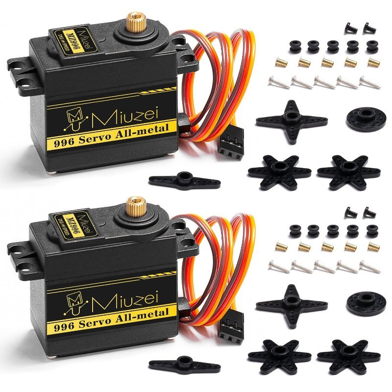
Metal gears, dual ball bearings, 180° travel, 4.8–6.6V. The default upgrade when an SG90 stops being enough.
Check Price on Amazon →Steppers: counted position, unlimited rotation, and a driver you have to tune
A stepper doesn’t spin so much as advance. A NEMA 17 — the “17” is the faceplate size, 1.7 inches square, not a model number — typically has a 1.8° step angle, which works out to exactly 200 discrete steps per revolution. Command 200 steps and you’ve turned one full turn, no sensor required. Command 50 and you’ve turned 90°. Nothing about that is limited to half a turn, and nothing about it drifts, as long as you never ask for more torque than the motor can deliver.
That’s the trade: a servo that gets overloaded fights and buzzes so you notice, while a stepper that gets overloaded quietly skips a step and every position after that is wrong by 1.8° with no error message. Steppers also can’t be driven from a simple H-bridge on their own — they need a dedicated driver that energizes the coils in the right sequence. The A4988 is the standard one: it takes up to 35V, handles about 1A per coil bare (2A with real cooling), and reduces the whole thing to two pins — a pulse on STEP moves one increment, the level on DIR picks the direction. It also does microstepping, splitting each 1.8° step into as many as 16 slices for 3,200 positions per revolution and much smoother, quieter motion.
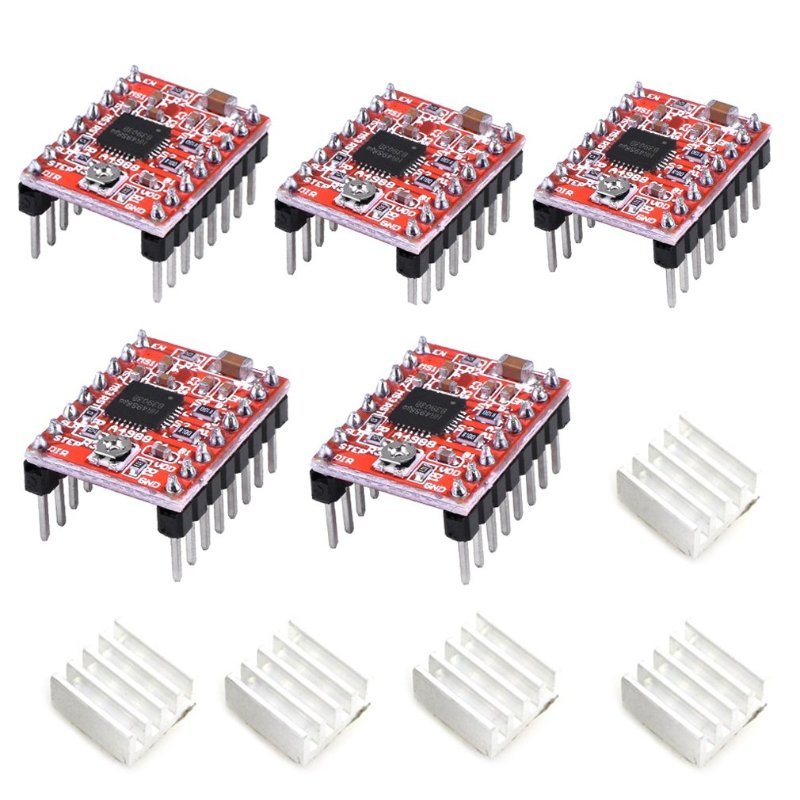
Before you run one, set the current limit — the tiny trimmer potentiometer on the A4988 sets a reference voltage that caps coil current, and shipping it untouched is how people cook motors and drivers on their first try. The STEP and DIR pins are happy with either 5V or 3.3V logic, so an ESP32 drives one as readily as an Uno does (if that distinction is new, see 5V vs. 3.3V Logic Levels, Explained).
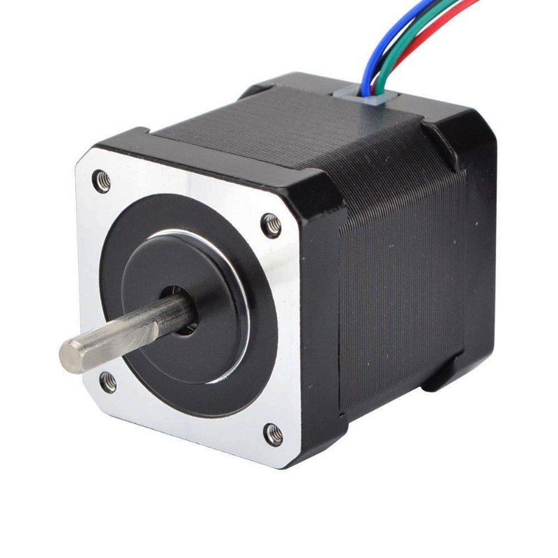
For the motor itself, this STEPPERONLINE NEMA 17 is the one that shows up in half the 3D printers on the planet: 59 N·cm (84 oz·in) of holding torque, 2.0A rated per phase, 1.4Ω coil resistance, 48mm body, and a 1-meter cable with a connector already crimped on so you’re not soldering four hair-thin leads.
200 steps per revolution, 84 oz·in holding torque, 4-lead bipolar with a 1m connectorized cable. Pair it with an A4988 and you have counted motion.
Check Price on Amazon →homing() routine that steps slowly in one direction until digitalRead() on the switch pin goes LOW, stops, and sets your position counter to zero. That single routine is the difference between a motor that turns and a machine that knows where it is at power-on — and it’s exactly how every 3D printer and CNC on earth starts a job.
The mistake all three share: power
None of these run off the Arduino’s 5V pin. Not one. The NEMA 17 wants 2A per phase from a 12V supply; the MG996R can pull about 2.5A at stall; four TT motors under load will brown out a USB port and reset your board mid-loop. Give the motors their own supply sized for stall current rather than running current, feed logic separately, and tie the two grounds together — without a common ground the driver has no shared reference for your STEP and DIR signals and the behavior gets bizarre in ways that look like code bugs.
The 10-second version
- Wheels, fans, pumps, anything that just spins: DC gearmotor. Cheapest, simplest, hardest to break.
- Arms, grippers, steering, camera mounts — anything that holds an angle: servo. Three wires, one library call, done.
- Sliders, dials, lead screws, anything that must land on a counted position and keep going past one turn: stepper plus driver.
- Still unsure? If you can describe the job without using the word “degrees,” you want a DC motor.
The expensive mistake isn’t picking the wrong motor — it’s picking the wrong one and then blaming your code for three evenings. Match the motor to the question the shaft has to answer, and most of the hard debugging disappears before you write a line.