A breadboard is the only thing on your desk with no documentation, no indicator light, and no way of telling you that you have wired it wrong. It is a slab of plastic with 830 holes in it. And most beginner circuits that quietly refuse to work — or, worse, get hot and then stop working permanently — fail because of a wrong assumption about which of those holes are electrically joined to which.
The good news is that the entire mental model fits in two sentences. Learn it once and you stop guessing.
What Is Actually Under the Plastic
Every hole sits on top of a springy metal clip, and those clips are ganged together in short strips buried inside the board. In the main working area, each strip ties exactly five holes together in a row. Push two component legs into holes in the same five-hole row and they are wired together — no solder, no jumper wire needed. Push them into adjacent rows and they are not connected at all, despite sitting a couple of millimeters apart. That gap between “touching” and “connected” is where most first circuits die.
The strips along the two outer edges work the opposite way. Those are the power rails (sometimes called bus strips), marked with a red + line and a blue or black − line, and they run the full length of the board rather than five holes at a time. They exist so you can bring 5V and ground onto the board once and then tap them from anywhere in your circuit.
That is the whole model: short rows running across the middle, long columns running down the sides. A full-size 830-point board breaks down as roughly 630 tie points of terminal area plus two 100-point distribution strips along the edges.
The Center Channel Is a Feature, Not a Gap
That trench down the middle of the board looks like wasted space. It is not. It is sized so that a DIP chip — a standard black rectangular integrated circuit with two rows of legs — straddles it, dropping its left pins into rows on one side and its right pins into rows on the other. Because the two halves are electrically separate, every pin gets its own private row you can wire to. Lay a chip flat on one side of the channel instead and you have shorted every opposing pin pair together.
The Rail Gap That Eats an Entire Afternoon
This one is worth committing to memory because it produces the most maddening symptom in beginner electronics. On many full-size breadboards, the power rails are broken in the middle into two independent half-length segments. Look closely at the printed red and blue lines along the edge: if there is a small break in the printed line partway down, the copper underneath is broken there too.
The result is a circuit that works perfectly on the left half of the board and is stone dead on the right half, with wiring that looks flawless. The fix takes ten seconds: run two short jumper wires across the break, one bridging the + segments and one bridging the − segments. Do it the day you unbox the board so you never have to rediscover it at 11pm.
How Much Current These Can Actually Take
Breadboard clips are generally rated around 1A at 5V, but that figure is a brief peak under ideal conditions, not a design target. For continuous draw, keep it under about 0.5A per row, and stay closer to 0.3–0.4A if you want the contacts to hold their grip over time. The rating also falls as voltage climbs — at 12V, treat 500mA as your ceiling.
The practical consequence: motors do not belong on breadboard power rails. A pair of DC gear motors hitting stall current will heat the clips, and heated clips relax permanently. The board still looks perfect afterward and will hand you intermittent connections for the rest of its life. Give motors their own supply, run them through a proper driver, and route only the low-current logic signals through the breadboard — see how motor drivers actually work for the wiring pattern.
The Four Ways Beginners Actually Destroy Parts
1. An LED with no current-limiting resistor. An LED is not a resistor; it does not politely draw less current when you give it more voltage. Wire a red LED (roughly a 2V forward drop) directly between a 5V pin and ground and the only thing limiting current is the internal resistance of the parts, which is not much. Put a 220Ω to 330Ω resistor in series, every time.
2. A backwards electrolytic capacitor. The tall cylindrical capacitors are polarized. The stripe down the side marks the negative leg, and the negative leg is usually the shorter one. Install it backwards and it will eventually vent — sometimes loudly.
3. Shorting the rails. A single stray jumper from the + rail to the − rail is a dead short across your supply. On a USB-powered Uno the onboard resettable fuse trips and you get away with it. On a bench supply or a lithium pack, something gets hot fast. Before you connect power, trace the two rails with your eyes and confirm nothing bridges them.
4. Feeding 5V into a 3.3V part. This is the one that silently kills ESP32 boards and SD card modules. If your board runs at 3.3V, its pins do not tolerate a 5V signal from an Uno. This deserves its own explanation, and it has one: 5V vs. 3.3V logic levels, explained.
The Board Worth Buying
Buy full-size boards, and buy more than one. The 400-point half-size boards that come bundled in starter kits run out of room the moment you add a second sensor, and the mini 170-point boards are only useful as satellites for a small sub-circuit. The other reason to own several: leaving a working circuit assembled while you build the next one is worth far more than the few dollars you save, because tearing down a circuit that works is how you lose an evening rebuilding it.
This post contains affiliate links. If you buy through them, this site earns a commission at no extra cost to you.
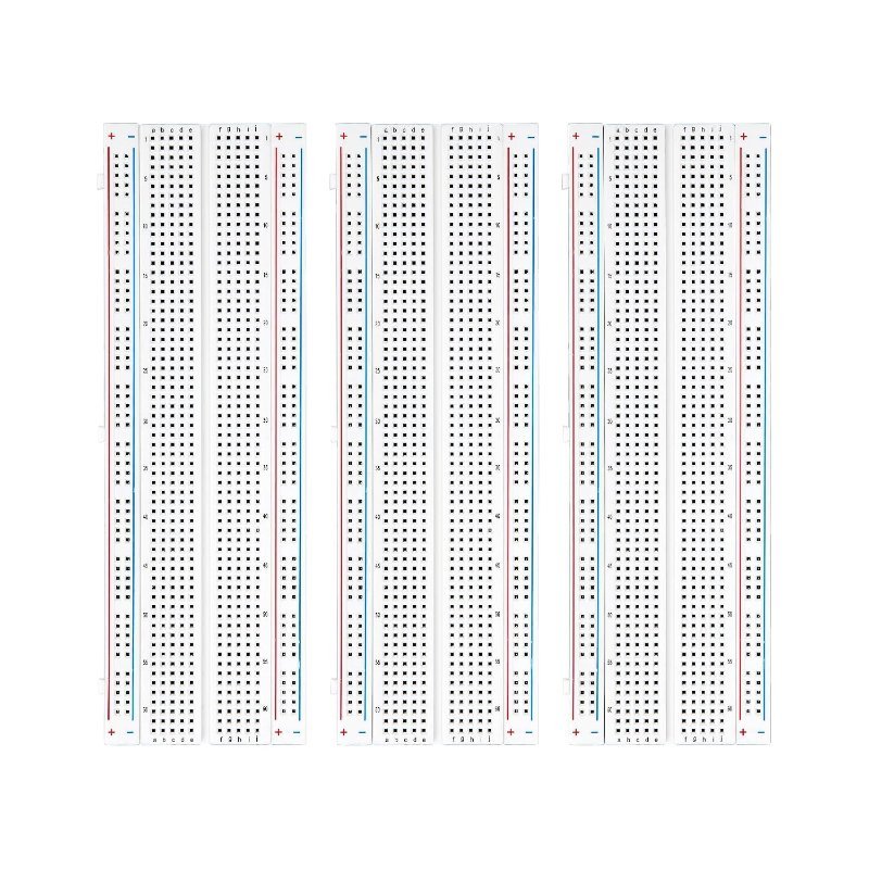
The ELEGOO three-pack is the straightforward answer. You get three full-size 830-point boards with four power rails, printed row numbers and column letters (which matter more than you would expect once you are debugging from a wiring diagram), side clips so you can gang boards together for a wider project, and adhesive backing for mounting to a chassis. Three boards for the price most single boards sell at.
Three full-size boards, four power rails each, numbered rows and lettered columns, side clips for joining boards. The default answer for anyone past their first starter kit.
Check Price on Amazon →None of this is complicated, which is precisely why it goes unexplained. Five holes across, full length down the sides, a split in the rails you have to bridge yourself, and a current budget measured in hundreds of milliamps rather than amps. Internalize those four things and the breadboard stops being the mysterious variable in your circuit.