Almost everyone building a first robot tries it once: wire the motor’s two leads straight into a pair of Arduino pins, call digitalWrite(9, HIGH), and wait for something to spin. What you get is a twitch, a warm microcontroller, and occasionally a board that never shows up over USB again. The motor driver is the part that belongs between those two things, and understanding why it exists is far more useful than copying somebody’s wiring diagram.
An Arduino Pin Is a Signal, Not a Power Supply
Each digital pin on an Arduino Uno is rated for 20 mA as a recommended operating condition, with 40 mA as the absolute maximum before you risk permanent damage to the ATmega328P. There’s a second ceiling people miss: roughly 100 mA total across an entire port — the groups of eight pins the chip is internally organized into — so spreading the load across several pins doesn’t rescue you either.
Now look at what a motor wants. One of the little yellow gearmotors from a robot car kit pulls somewhere around 150-250 mA spinning freely at 6 V, and several times that at the moment you switch it on or when you pinch the wheel to a stop — stall current on those is commonly quoted near 1 A. That isn’t slightly over budget. That’s an order of magnitude past what the pin can source.
There’s a second problem, and it’s the one that actually kills boards. A motor is a coil of wire moving through a magnetic field, which means it works as a generator whether you asked it to or not. Cut current to an energized coil and the collapsing field dumps a voltage spike back down the wires — reversed in polarity, and potentially well above your supply voltage. That’s back-EMF. Feed it into a microcontroller pin and you’re not taking a risk so much as scheduling a failure.
The H-Bridge: Four Switches Shaped Like a Letter
An H-bridge is four switches arranged with the motor sitting in the crossbar between them. Sketch it and the shape is roughly the letter H, which is where the name comes from. Close the top-left and bottom-right switches and current runs through the motor left to right. Close top-right and bottom-left instead and current runs right to left, and the motor turns the other way. That’s the entire trick — you never reverse the power supply, you reverse which path through the motor is open.
Two rules fall straight out of that arrangement. First, never close both switches on the same vertical leg at once: that’s a direct short from supply to ground through two transistors, and it’s called shoot-through for good reason. Competent driver chips include logic to prevent it. Second, the assembly needs somewhere for back-EMF to go, which is what flyback diodes are for — a diode across each switch gives the collapsing coil current a loop to burn itself off in instead of a path into your electronics. Worth knowing: the L298N chip itself doesn’t contain those diodes. The familiar red breakout module adds eight of them on the board, which is one of several reasons to buy the module rather than the bare IC.
Speed Comes From PWM, Not From a Voltage Knob
Direction is only half the job. Speed comes from the driver’s enable pin, which takes a PWM signal — pulse width modulation, a way of faking an analog voltage by flipping a digital output on and off very quickly. On an Uno, analogWrite(pin, 128) holds the pin HIGH about half the time and LOW the other half, cycling at roughly 490 Hz on most pins (pins 5 and 6 run closer to 980 Hz). The motor’s own inertia and inductance smooth those pulses into something that behaves like half voltage, so it turns at roughly half speed. The range is 0-255, not 0-100, which trips people up constantly.
One practical note: below about 20% duty cycle a loaded motor often won’t move at all, because there isn’t enough average torque to break static friction. That’s not a broken driver. That’s friction.
The Board Nearly Everyone Starts With
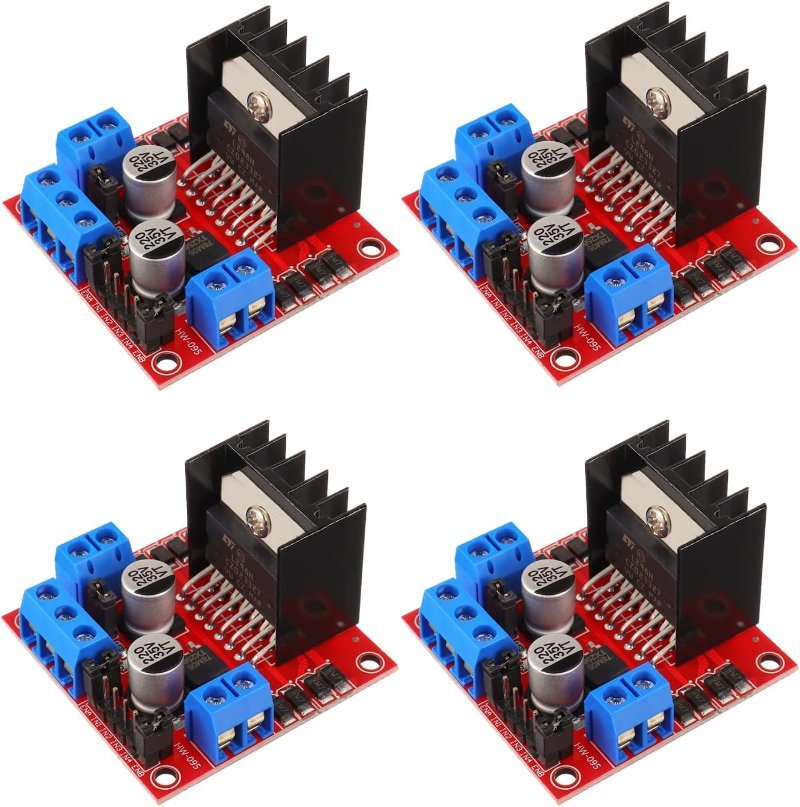
For a first driven-wheel project, the L298N module is the board in every tutorial, and there’s a decent case for starting there regardless. It drives two motors independently at up to 2 A each, accepts a motor supply from roughly 5 V up to 35 V, and its control pins are plain 5 V logic that an Uno talks to directly. The screw terminals also forgive the kind of wiring you do before you own a soldering iron.
This post contains affiliate links. If you buy through them, this site earns a commission at no extra cost to you.
Two channels at 2 A each, 5 V logic inputs, screw terminals, onboard flyback diodes and heatsink. Inefficient by modern standards, but rugged, cheap, and the board every tutorial and robot car kit assumes you have.
Check Price on Amazon →Why That Voltage Drop Is the L298N’s Real Flaw
The L298N switches with bipolar junction transistors, which impose a fixed voltage drop no matter how little current you’re pulling. Push 2 A through both channels and you’re dissipating something on the order of 4 W as heat — hence the heatsink — while on a 6 V battery pack, losing 2 V to the driver means the motors themselves never see more than about 4 V. Efficiency lands somewhere near 70%, and the battery drains accordingly. This is the actual answer to most “why is my robot car so slow and why is the driver so hot” questions.
The TB6612FNG fixes it by switching with MOSFETs instead. A MOSFET behaves like a small resistance rather than a fixed drop, so at the currents a hobby robot actually pulls, the loss is closer to 0.5 V — efficiency in the mid-90s, no heatsink needed, and a board a fraction of the size. The tradeoff is headroom: 1.2 A continuous per channel (3.2 A peak) against the L298N’s 2 A, and a motor supply ceiling of 13.5 V instead of 35 V. For a battery-powered robot on small gearmotors, that’s a trade worth taking, and the control signals are similar enough that swapping mostly means moving wires.
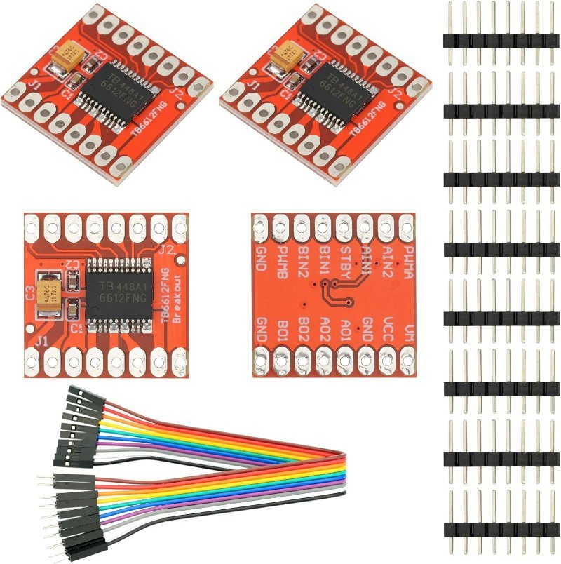
MOSFET output stages, roughly 0.5 V of drop instead of 2 V, and a separate logic supply pin that’s happy at 3.3 V. Lower current ceiling than the L298N, but the right choice the moment your robot runs on batteries.
Check Price on Amazon →The Four Connections You’ll Meet Immediately
- IN1 / IN2 (and IN3 / IN4) — direction. One HIGH and one LOW turns the motor one way; flip them to reverse. Both the same is brake or coast, depending on the chip.
- ENA / ENB — speed, via PWM. On the L298N module these ship with a jumper tying them to 5 V, meaning full speed always. Pull that jumper before you spend an hour wondering why
analogWrite()does nothing. - Common ground — the Arduino’s GND and the driver’s GND must be tied together, even when the motors run off a separate battery. Without a shared reference, HIGH and LOW don’t mean anything to the driver.
- The 5 V jumper — on the L298N module this enables an onboard 78M05 regulator that can power your Arduino from the motor supply. It’s only good for input up to 12 V. Above that, pull the jumper and power the logic side separately, or you’ll cook the regulator.
One more, if you’re driving from an ESP32 or a Pico rather than an Uno: those output 3.3 V logic, not 5 V. The L298N’s inputs will usually read 3.3 V as HIGH, but “usually” is carrying weight in that sentence — read our breakdown of 5V vs. 3.3V logic levels before you assume it’ll be fine. The TB6612FNG sidesteps the question entirely with its separate logic supply pin.
The Short Version
A motor driver does three jobs: it keeps a delicate microcontroller pin away from a current-hungry inductive load, it reverses direction without reversing the power supply, and it turns a PWM signal into speed. The L298N does all three cheaply and forgivingly. The TB6612FNG does all three efficiently. Neither one is optional — the alternative to a motor driver isn’t a simpler circuit, it’s a dead board.